Category: STEM (Science, Technology, Engineering and Mathematics)
ORIGINAL
Efficiency of Steel Fibers in Improving the Performance of Concrete Beams without Shear Reinforcement
Eficacia de las fibras de acero para mejorar el comportamiento de vigas de hormigón sin armadura de cortante
Huda S. Merdas1 *, Muhaned A. Shallal1 *
1Civil Eng. Dep. College of Engineering-University of Al. Qadisiyah, Iraq.
Cite as: Merdas HS, Shallal MA. Efficiency of Steel Fibers in Improving the Performance of Concrete Beams without Shear Reinforcement. Salud, Ciencia y Tecnología - Serie de Conferencias. 2024; 3:830. https://doi.org/10.56294/sctconf2024830
Submitted: 23-01-2024 Revised: 06-04-2024 Accepted: 02-06-2024 Published: 03-06-2024
Editor: Dr.
William Castillo-González ![]()
Note: paper presented at the 3rd Annual International Conference on Information & Sciences (AICIS’23).
ABSTRACT
This research aims to experimentally study the shear strength of steel fiber concrete beams without shear reinforcement (stirrups). Parameters of the study include two compressive strength (20, 50 MPa), three ratios of flexural reinforcement (0,77, 1,14, 1,54 %), two ratios of shear span to effective depth (a/d = 2,3), and two types of aggregates (Natural coarse aggregate and recycled aggregate (crushed bricks)) with and without steel fibers. Three ratios of the volume fraction of steel fiber are used in the study (0, 0,5, 1 %). All specimens were loaded to failure. Thirteen specimens of concrete beams without shear reinforcement were tested with dimensions (200 x 300 mm) for cross-section (width, depth) and length (2000 mm). The beams were examined to evaluate the effect of each of the above variables on the shear strength and behavior of the beams. All beams are designed to fail with shear stress (without shear reinforcement) under a two-point load test. After obtaining and analyzing the practical results, a set of conclusions were made clear, as the results showed that increasing the compressive strength leads to increases in the maximum shear strength by (60 %). Also, the increase in the flexural reinforcement causes increases in the maximum shear strength by (53 %). As for the ratio of shear span to effective depth, the effect is the opposite, the increasing from 2 to 3 leads to a decrease in shear strength by (30 %). As for the type of aggregate, replacing 50 % of the natural coarse aggregate with recycled aggregate (crushed bricks) leads to a decrease in the maximum shear strength by (10,5 %). The results also show the efficiency of the steel fibers by improving the behavior of the beams under loading, as the addition of steel fibers by 0,5 % increases the maximum shear strength by (18 %). Still, when the steel fibers are 1 % of the volume of concrete, the amount of improvement in shear strength ranges from (30-50 %) despite the difference in the details of the specimens.
Keywords: Steel Fiber; Shear Reinforcement; Recycled Aggregate; Concrete Beam; Shear Span to Effective Depth; Longitudinal Reinforcement.
RESUMEN
Esta investigación pretende estudiar experimentalmente la resistencia a cortante de vigas de hormigón con fibras de acero sin armadura de cortante (estribos). Los parámetros del estudio incluyen dos resistencias a compresión (20, 50 MPa), tres relaciones de refuerzo a flexión (0,77, 1,14, 1,54 %), dos relaciones de luz de cortante a profundidad efectiva (a/d = 2,3), y dos tipos de áridos (árido grueso natural y árido reciclado (ladrillos triturados)) con y sin fibras de acero. En el estudio se utilizan tres relaciones de la fracción volumétrica de la fibra de acero (0, 0,5, 1 %). Todos los especímenes se cargaron hasta el fallo. Se ensayaron trece probetas de vigas de hormigón sin refuerzo de cortante con dimensiones (200 x 300 mm) para la sección transversal (anchura, profundidad) y longitud (2000 mm). Las vigas se examinaron para evaluar el efecto de cada una de las variables anteriores sobre la resistencia a cortante y el comportamiento de las vigas. Todas las vigas están diseñadas para fallar con esfuerzo cortante (sin refuerzo cortante) bajo un ensayo de carga en dos puntos. Tras la obtención y análisis de los resultados prácticos, se pusieron de manifiesto una serie de conclusiones, ya que los resultados mostraron que el aumento de la resistencia a compresión conduce a aumentos de la resistencia máxima a cortante en un (60 %). Asimismo, el aumento de la armadura de flexión provoca incrementos en la resistencia máxima a cortante del (53 %). En cuanto a la relación entre la luz de cortante y la profundidad efectiva, el efecto es el contrario, el aumento de 2 a 3 conduce a una disminución de la resistencia al cortante en un (30 %). En cuanto al tipo de árido, la sustitución del 50 % del árido grueso natural por árido reciclado (ladrillos triturados) conduce a una disminución de la resistencia máxima al corte del (10,5 %). Profundidad Efectiva; Refuerzo Longitudinal. Los resultados también muestran la eficacia de las fibras de acero al mejorar el comportamiento de las vigas bajo carga, ya que la adición de fibras de acero en un 0,5 % aumenta la resistencia máxima a cortante en un (18 %). Aun así, cuando las fibras de acero son el 1 % del volumen de hormigón, la cantidad de mejora en la resistencia a cortante oscila entre el (30-50 %) a pesar de la diferencia en los detalles de los especímenes.
Palabras clave: Fibra de Acero; Refuerzo a Cortante; Árido Reciclado; Viga de Hormigón; Luz de Cortante a Profundidad Efectiva; Refuerzo Longitudinal.
INTRODUCTION
Reinforced concrete (RC) is the most widely used structural material in the world, as it is used in various structural buildings. It consists of two materials (concrete and steel) with different mechanical properties. Concrete is known to be strong in compression resistance but weak in tensile strength. Therefore, the use of steel in concrete is required to increase its tensile strength. Reinforcement is of two types longitudinal and transverse (stirrups) reinforcement, the former is used to resist tensile strength and the latter is used to resist shear strength. In addition, casting concrete with closely spaced stirrups may be difficult, resulting in cavities and a poor bond between the concrete and reinforcing bars. Therefore, in the past four centuries, many studies have been conducted to replace transverse reinforcement that resists shearing with fiber, using randomly oriented steel fibers to improve the shear strength represents a good alternative method to increase the shear strength. There are many continual studies over the years specialized in studying the effect of steel fiber volume fraction on the mechanical properties of concrete and produce steel fiber reinforced concrete (SFRC).(1,2,3,4,5,6,7,8,9,10,11,12,13,14,15,16,17,18,19,20,21) The increase in shear strength can vary drastically depending on the beam geometry and material properties, Li et al.(3) showed that with increasing beam depth, the average shear stress at failure decreases, Muhaned(22) based his study on a database of 175 beams from previous studies and demonstrated through his study that the effect of beam width and effective depth on shear strength is greater compared to the effect of compressive strength of concrete, longitudinal reinforcement, and shear span to effective depth ratio for concrete beams without shear reinforcement. Narayanan et al.(1) found that steel fibers increase the shear strength of concrete by a range of 13-170 %. Much previous research dealt with the study of variables that affect shear strength. It is well established from many previous studies that the maximum shear strength of steel fiber reinforced concrete beams rises with rising flexural reinforcement ratio (ρ), the concrete compressive strength (fc'), and reducing shear span depth ratio (a/d).(1,2,4) Kwak et al.(6) were shown that the addition of steel fibers increases the tensile strength of the concrete, which in turn improves the behavior of the failure pattern of the beam, as the addition of fibers changes the failure pattern from shear failure to flexure failure, in addition, when the a/d ratio is less than 2 the strength of beam increases by 69-80 %, while at large a/d ratio, the increase in the beam strength was smaller(22-38 %). The authors show that reverse loading can reduce the shear strength of normal concrete, but by adding fibers, it can be noticed an increase in shear capacity under this type of loading, and it also shows that the effect of compressive strength on the maximum shear strength of fiber-reinforced concrete is small.(23) After that, many studies appeared on the recycling of building materials, including, iron,(24) wood,(25) brick,(15) and block concrete.(26) Most of the studies on recycling focused on recycling concrete and the use of recycled coarse aggregates in it, these studies found that the use of recycled aggregates weakens the properties of the produced concrete.(26,33) After that, the studies developed by treating the recycled aggregates. Many authors treated the recycled aggregate before using it in the production of concrete and proved through the results that there is an improvement in the properties of the produced concrete compared to the concrete with untreated aggregate.(34,39) Subsequently, the researchers were keen to adopt other methods to improve the properties of the produced concrete, including the use of steel fibers, the authors showed that the use of fibers significantly improves the properties of concrete produced from recycled aggregates.(40,33) Despite the many studies above on fiber concrete, it is still under study to clarify its behavior and study properties, and research is continuing to develop it. This research aims to study the shear strength of reinforced concrete under the influence of the steel fiber volume fraction, the compressive strength of concrete, the ratio of longitudinal reinforcement, and the effect of shear span to effective depth ratio. Finally, a study of the shear strength of recycled concrete by replacing 50 % of coarse aggregate with recycled aggregate (crushed bricks) of the same size, with the effect of the steel fiber volume fraction.
Test Program
Thirteen reinforced concrete beams without stirrups were tested until failure to estimate the effect of each of the steel fiber volume fraction (Vf), the ratio of longitudinal reinforcement (ρ), the compressive strength of concrete, shear span to effective depth ratio (a/d), as well as the effect of recycled aggregates by replacing 50 % of natural coarse aggregates with recycled aggregate (crushed bricks R) on shear strength of the beam. Table 1 explains the details of the test beam. Seven different concrete mixtures were prepared, the first four specimens were prepared from the first mixture with the symbol (F50S1NBxadx) prepared with a compressive strength of approximately (50 MPa), steel fiber volume fraction (S=1 %) by the volume of the concrete, using natural aggregate (N), with three different percentages of longitudinal reinforcement (Bx=0,77, 1,15, and 1,54 %) (2, 3, and 4 Փ16 bars), and two values of the a/d ratio (=2, 3). One specimen for each of the reinforcement ratios (0,77, 1,15 %) with a/d (2) and two specimens for the reinforcement ratio (1,54 %) with a/d (2,3). The second mixture (F50S0NBxadx) has the same specifications as the first mixture but without steel fiber. The third mixture (F50S0.5NB4ad2) compressive strength (50MPa), steel fiber volume fraction (S=0,5 %), natural aggregate (N), reinforcement longitudinal (B=1,54 %) (4Փ16 bars), with a/d (ad=2). The fourth mixture (F50S1RB4ad2) compressive strength (50MPa), steel fiber volume fraction (S=1 %), crushed bricks (R) 50 %, reinforcement longitudinal (B=1,54 %) (4Փ16 bars), and a/d (ad=2). The fifth mixture (F50S0RB4ad2) has the same specifications as the fourth mixture but without steel fiber. The sixth mixture (F20S1NB4ad2) compressive strength is approximate (20MPa), steel fiber (S=1 %), natural aggregate (N), reinforcement longitudinal (B=1,54 %) (4Փ16 bars), and a/d (ad=2). The seventh mixture (F20S0NB4ad2) has the same specifications as the sixth mixture but without steel fiber.
As shown in figure 1, all beams are rectangular in cross-section (200x300 mm), with an effective depth of 262 mm with a concrete cover of 20 mm from all sides, for flexural reinforcement Փ16 was used in the tension zone and 2 Փ10 in the compression zone and use for each beam three stirrups Փ10 in each end and mid-span. The support that was adopted in this examination is simply supported by a roller at one end and a hinge at the other, the test method used is the two-point load.
Material Properties
Concrete mixes M50, and M20 were produced using sulfate-resistant cement this type of cement was used as it is of better quality and to avoid the effect of salts present in the raw materials. The natural sand is confined in zone III and has a fineness modulus of 2,1, the normal coarse aggregate with size 5-20 mm, and recycled crushed bricks confined on a sieve (4,75, 2,36, and 10 mm), in a saturated and dry surface condition. Table 2 shows the quantity of materials used in each mixture. The flexural reinforcement Փ16 had a yield stress of (606 MPa) and an ultimate strength of (691MPa), and Փ10 had a yield stress of (617MPa) and an ultimate strength of (707MPa). The type of steel fiber used in this research is hooked-end steel fiber, with a diameter of 0,51 mm, length of 30 mm, and aspect ratio of 60. The tensile strength of the steel fibers was 1300 MPa. The type of high-range water-reducing admixture was Hyperplastic PC175 to enhance the workability of M50. The results are shown in table 3.
|
Table 1. The details of the test beams |
|||||||||
|
No. |
ID |
b(mm) |
h(mm) |
fc (MPa) |
Steel fiber % |
ρ % |
a/d |
Type of aggregate |
|
|
1 |
F20S1NB2ad2 |
200 |
300 |
20 |
1 |
0,77 |
2 |
Normal coarse |
|
|
2 |
F20S0NB2ad2 |
200 |
300 |
20 |
0 |
0,77 |
2 |
Normal coarse |
|
|
3 |
F50S0NB4ad3 |
200 |
300 |
50 |
0 |
1,54 |
3 |
Normal coarse |
|
|
4 |
F50S0NB4ad2 |
200 |
300 |
50 |
0 |
1,54 |
2 |
Normal coarse |
|
|
5 |
F50S0NB3ad2 |
200 |
300 |
50 |
0 |
1,15 |
2 |
Normal coarse |
|
|
6 |
F50S0NB2ad2 |
200 |
300 |
50 |
0 |
0,77 |
2 |
Normal coarse |
|
|
7 |
F50S0.5NB4ad2 |
200 |
300 |
50 |
0,5 |
1,54 |
2 |
Normal coarse |
|
|
8 |
F50S1NB4ad3 |
200 |
300 |
50 |
1 |
1,54 |
3 |
Normal coarse |
|
|
9 |
F50S1NB4ad2 |
200 |
300 |
50 |
1 |
1,54 |
2 |
Normal coarse |
|
|
10 |
F50S1NB3ad2 |
200 |
300 |
50 |
1 |
1,15 |
2 |
Normal coarse |
|
|
11 |
F50S1NB2ad2 |
200 |
300 |
50 |
1 |
0,77 |
2 |
Normal coarse |
|
|
12 |
F50S0RB4ad2 |
200 |
300 |
50 |
0 |
1,54 |
2 |
Crush brick+ Normal coarse |
|
|
13 |
F50S1RB4ad2 |
200 |
300 |
50 |
1 |
1,54 |
2 |
Crush brick+ Normal coarse |
|
|
Table 2. The amounts of materials of mixes used throughout this study |
|||||||
|
Mixture |
Cement content, (kg/m3) |
Aggregate content |
Crushed Brick, (kg/m3) |
Steel fibers content, (kg/m3) |
Water cement ratio, % |
Water-reducing admixture (%) |
|
|
Sand, (kg/m3) |
Gravel, (kg/m3) |
||||||
|
F20S0N |
365 |
830 |
960 |
- |
0 |
55 |
- |
|
F20S1N |
365 |
830 |
960 |
- |
78 |
55 |
- |
|
F50S0N |
500 |
668 |
1040 |
- |
0 |
30 |
0,055 |
|
F50S0.5N |
500 |
668 |
1040 |
- |
39 |
30 |
0,045 |
|
F50S1N |
500 |
668 |
1040 |
- |
78 |
30 |
0,045 |
|
F50S0R |
500 |
668 |
520 |
885 |
0 |
30 |
0,012 |
|
F50S1R |
500 |
668 |
520 |
885 |
78 |
30 |
0,012 |
Testing Procedure
All specimens were tested in the structural laboratory of the Civil Department at the University of Al- Qadisiyah. By using the universal hydraulic testing device with a 1000 kN capacity. The clear span between supports is 1800 mm with two-point loading with shear span to effective depth ratios (a/d) is 2,3. A digital dial gauge was used to record mid-span deflection. Figure 2 shows the testing device.

Figure 1. The details of the models

Figure 2. Tested device of beams
RESULTS AND DISCUSSION
After obtaining the experimental test results for thirteen samples of reinforced concrete beams without shear reinforcement (stirrups), several results were studied, including the first shear crack load, ultimate load, and failure pattern for each sample under the influence of each of the compressive strength, flexural reinforcement, shear span to the effective depth ratio, and the type of aggregate with and without steel fibers. Table 3 shows the test results for the specimens. The failure pattern of all samples can be determined through what has been observed for the behavior of the samples during loading, despite the different details of the samples, the failure pattern was uniform for all samples, but the speed of cracks appearing and their development is affected by the presence of steel fibers, where we notice in all samples that after applying a percentage of the loads, cracks begin to appear in the zone between the points of the loading and it is called flexural cracks, with the continuous increase in the percentage of the applied loads. It can be noticed the continued appearance of cracks along the beam until it reaches the zone confined between the support and the point loading. These cracks are called shear cracks, and with the appearance of the diagonal shear crack, the sample fails. This failure pattern is identical for all samples, but the difference is in the speed of growth and development of cracks, as the samples that do not contain steel fibers, we notice that their resistance to crack growth and development is weak, and this leads to the failure of the sample directly without any initial indications, but with the presence of steel fibers spread throughout the section, it can be noticed that there is a delay in the growth of these cracks, as the fibers act as bridges linking the two ends of the crack and work to transfer the stresses that it cuts to the concrete, as it has a high tensile strength of up to 1300 MPa. This behavior leads to a delay in the development of cracks Thus, it can transform concrete from a brittle material into a flexible material capable of withstanding tensile stresses, in the following, it will discuss the effect of each of the parameters that have been studied in this research.
|
Table 3. Result of tested beams |
|||||
|
No. |
ID |
First shear crack load(kN) |
Ultimate Load (kN) |
Failure mode |
|
|
1 |
F20S0NB2a2 |
135 |
136 |
shear failure |
|
|
2 |
F20S1NB2a2 |
142 |
207 |
shear failure |
|
|
3 |
F50S0NB4a3 |
135 |
235 |
shear failure |
|
|
4 |
F50S0NB4a2 |
202 |
334 |
shear failure |
|
|
5 |
F50S0NB3a2 |
202 |
310 |
shear failure |
|
|
6 |
F50S0NB2a2 |
154 |
218 |
shear failure |
|
|
7 |
F50S0.5NB4a2 |
286 |
395 |
shear failure |
|
|
8 |
F50S1NB4a3 |
237 |
294 |
shear failure |
|
|
9 |
F50S1NB4a2 |
307 |
437 |
shear failure |
|
|
10 |
F50S1NB3a2 |
232 |
338 |
shear failure |
|
|
11 |
F50S1NB2a2 |
186 |
318 |
shear failure |
|
|
12 |
F50S0RB4a2 |
206 |
302 |
shear failure |
|
|
13 |
F50S1RB4a2 |
246 |
398 |
shear failure |
|
Effect of Compressive Strength
To follow up on the effect of compressive strength on the behavior of the specimens, four specimens were adopted to study the effect of this parameter (F50S0NB2a2, F50S1NB2a2, F20S0NB2a2, and F20S1NB2a2) with constant the other parameters. In this section, two different grades of compressive strength (20, and 50MPa) were adopted, the rest of the other details of the specimens were mentioned above. Figure 3 shows the failure pattern of the specimens after the examination. Figure 4, and figure 5 show the load-deflection curves for specimens without steel fibers and with steel fibers, respectively. The results of the experimental test show that the specimen (F50S0NB2a2) with compressive strength (50MPa) and without steel fibers shows higher strength to applied loads compared to the specimen (F20S0NB2a2) with compressive strength (20MPa) and without steel fibers. Figure 4 shows at 72 kN, the mid-span deflection of beam (F20S0NB2a2) was 1,43 mm, whereas beam (F50S0NB2a2) showed a mid-span deflection of 1,28 mm only, it is clear that with an increase in the compressive strength, the shear capacity of the beam increases, as the maximum shear capacity and first shear crack of the (F50S0NB2a2) increased by about 60 % and 14 %, respectively when compared with (F20S0NB2a2).
As well as for the beam with steel fibers, specimens with steel fiber have the same behavior compared with specimens without steel fiber, where the maximum shear capacity and first shear crack of the (F50S1NB2a2) increased by about 54 % and 30 %, respectively when compared with (F20S1NB2a2). the results explain that samples with steel fiber have higher strength and durability than the samples without steel fibers, as the maximum shear capacity of the (F50S1NB2a2) and (F20S1NB2a2) increased by about 45,8 %, and 52 % when compared with (F50S0NB2a2), and (F20S0NB2a2), respectively.

Figure 3. Crack pattern of test specimens under the effect of compressive strength with and without steel fiber
Effect of Steel Fiber
This parameter was adopted with different percentages (0, 0,5, and 1 %) of the concrete volume, with the fixedly of the other details mentioned above. The relationship between applied loads with mid-span deflection is represented in figure 6. It is evident through the behavior of the samples during the examination that the higher the percentage of steel fibers in the sample, the greater the strength and durability of the model in absorbing the stresses imposed on it. Figure 6 shows at (200kN) the mid-span deflection of beams is (5,3, 4,45, 3,9 mm) in the samples (F50S0NB4a2) (F50S0.5NB4a2) (F50S1NB4a2), respectively. it was observed that the fibrous beams showed a higher toughness than those of non-fibrous beams, particularly when Vf of 1 % was added. The maximum shear capacity and the first shear crack load are listed in table 3. When comparing the specimens (F50S0.5NB4a2) and (F50S1NB4a2) with the reference specimen (F50S0NB4a2), the results show that with the increase in the proportion of steel fibers, the maximum shear capacity and first shear crack load of the models increases. The maximum shear capacity increases by (18 %) and (30,8 %) respectively, as well as for the first shear crack load (6,7 %) and (14,5 %). The reason for the efficiency of the steel fibers in improving the behavior of the samples is due to their widespread distribution within the concrete matrix and their hooked ends, which give them additional strength by interlocking them inside the concrete matrix, and this causes a delay in the development of crack growth and gives the sample more durability in resistance stresses. Figure 7 shows the failure pattern of the specimens after the examination.

Figure 4. Effect of compressive strength without steel fiber on load-mid span deflection

Figure 5. Effect of compressive strength with steel fiber on load-mid span deflection

Figure 6. Effect of the volume fraction of steel fiber on load-mid span deflection

Figure 7. Crack patterns of test specimens under effect of volume fraction of steel fiber
Effect of Longitudinal Reinforcement
To study the effect of this parameter on the behavior of specimens under loading, six specimens were adopted with three different ratios of flexural reinforcement (0,77, 1,15, 1,54 %) (2, 3, and 4 Փ16) with constant other details of the specimens mentioned in the previous section. Specimens are (F50S0NB2a2), (F50S0NB3a2), and (F50S0NB4a2) without steel fibers while specimens (F50S1NB2a2), (F50S1NB3a2), and (F50S1NB4a2) with steel fibers 1 % by the volume of concrete. Table 3 shows the results of the experimental test of the specimens. Figure 8 and figure 9 show the failure pattern of the specimens after the examination. Figure 10 and figure 11 show the load-deflection curves for the specimens without and with the steel fibers, respectively. Through figure 10 at (83kN) we notice that the deflection recorded (1,61, 1,5, 1,78 mm) for the specimens (F50S0NB2a2), (F50S0NB3a2), (F50S0NB4a2), respectively, while figure 11 shows the deflection recorded for the steel fiber-reinforced specimens (F50S1NB2a2), (F50S1NB3a2), (F50S1NB4a2) is (5,15, 2,55, 1,38 mm), respectively. The results in table 3 show that the maximum shear capacity, increases with the increase in the flexural reinforcement ratio, as the specimens (F50S0NB4a2), (F50S0NB3a2) recorded an increase of (53, and 42 %), respectively, compared to the reference specimen (F50S0NB2a2), and also for the first shear crack load, the percentage increase was recorded (74, 31 %) for the specimens (F50S0NB4a2), (F50S0NB3a2), respectively, compared to the reference specimen (F50S0NB2a2). As for the specimens that contain steel fibers 1 % by volume, we note that they have the same behavior as the samples without steel fibers, but with higher rates of increase due to the presence of steel fibers that contribute to increasing the strength of the specimens. The finding shows that the maximum shear capacity of specimens (F50S1NB2a2), (F50S1NB3a2), and (F50S1NB4a2) increases by (30,8, 9,1, and 45,87 %) when compared to the same specimens without steel fibers (F50S0NB2a2), (F50S0NB3a2), and (F50S0NB4a2) respectively. The ability to absorb the load of specimens reinforced with steel fibers is higher than that of specimens without steel fibers, and an explanation for this is that the steel fibers present in the tensile region give additional strength to flexural reinforcement in resisting the applied stresses.

Figure 8. Crack pattern of test specimens under the effect of flexural reinforcement with steel fiber
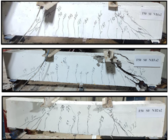
Figure 9. Crack pattern of test specimens under the effect of flexural reinforcement without steel fiber
Effect of Shear Span to Effective Depth Ratio (a/d)
To explain the influence of the shear span to effective depth ratio on the behavior of concrete beams four specimens F50S0NB4a2, F50S0NB4a3 (without steel fiber), F50S1NB4a2, and F50S0NB4a3 (with steel fiber 1 % by the volume of concrete), were utilized with two different ratios of shear span to effective depth (a/d) (2 and 3), with the stability of other details of the specimens mentioned in the above. Table 3 shows the results of the experimental tests of those samples. Figure 12 and figure 13 show the failure pattern of the specimens after the examination. Figure 14 and figure 15 explain the load-deflection curve of these samples with and without steel fiber, respectively. Figure 15, at the same load of 80kN, it can be observed that the deflection in samples without steel fiber F50S0NB4a3 and F50S0NB4a2 were 1,85 mm and 1,71 mm respectively, while for specimens with steel fiber (F50S1NB4a3 and F50S1NB4a2) the deflection recorded are (2,25, 1,33 mm), figure 14 gives a negative indicator for increasing (a/d), also show that with its increase, the shear capacity decreases by 30 %, as well as for the first shear crack load, the percentage of decrease is about 32 % for the specimen (F50S0NB4a3) when compared with the reference specimen (F50S0NB4a2). As for the presence of steel fibers, we note that the decrease in the maximum shear capacity by the same percentage is approximately 30 %. As for the first shear crack load, the percentage decrease is about 22 %, and an explanation for this is that by increasing the ratio of the shear span to the effective depth, the distance between the centers of load shedding will decrease and it will almost be one a central force, thus interaction will occur between shear and flexural failure.

Figure 10. Effect of flexural reinforcement without steel fiber on load-mid span deflection

Figure 11. Effect of flexural reinforcement with steel fiber on load-mid span deflection

Figure 12. Crack pattern of test specimens under effect of shear span to effective depth ratio without steel fiber

Figure 13. Crack pattern of test specimens under effect of shear span to effective depth ratio with steel fiber
Effect of Aggregate Type
To discuss the influence of the type of aggregate on the behavior of concrete beams, four specimens F50S0NB4a2, F50S0RB4a2 (without steel fiber), F50S1NB4a2, F50S1RB4a2 (with steel fiber 1 % by the volume of concrete), were utilized with two different types of aggregate (normal coarse aggregate (N), and recycled bricks aggregate (R)), with the stability of other details of the specimens mentioned in the above research. Table 3 lists the results of the experimental tests of those specimens. Figure 16 and figure 17 show the failure pattern of the specimens after the examination. Figure 18 and figure 19 explain the load-deflection curve of these specimens with and without steel fiber, respectively. The drawn curvatures show that at the load (80kN), the deflection (1,71, 1,46 mm) of the specimens without steel fiber (F50S0NB4a2, F50S0RB4a2) respectively, while for the specimens reinforced with steel fibers (F50S1NB4a2, F50S1RB4a2) the deflection recorded (1,33, 0,99 mm) respectively. Hence it is clear that replacing 50 % of the natural coarse aggregate with the recycled aggregate (crushed bricks) leads to a decrease in the maximum shear capacity by (10,5 %) as well as for the first shear crack load is reduced by (47 %). However, with the presence of steel fibers, the results show that maximum shear capacity decreases by (9 %) and the first shear crack load decreases by (19 %). An explanation for the above results is that the bricks made of fired clay are less dense, less durable, and have higher porosity than the natural coarse aggregate, and therefore will affect the matrix concrete being part of it. However, the decrease percentages are reduced by the presence of steel fibers, as it contributes to improving the internal bonding of the concrete matrix and makes it stronger and more durable in resisting loads.

Figure 14. Effect of shear span to effective depth ratio with steel fiber on load-mid span deflection

Figure 15. Effect of shear span to effective depth ratio without steel fiber on load-mid span deflection

Figure 16. Crack pattern of test specimens under effect of type of aggregate with steel fiber
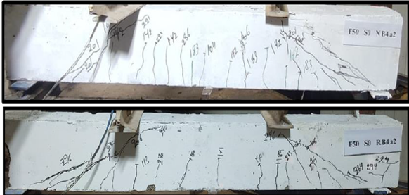
Figure 17. Crack pattern of test specimens under effect of type of aggregate without steel fiber

Figure 18. Effect of type of aggregate with steel fiber on load-mid span deflection

Figure 19. Effect of type of aggregate without steel fiber on load-mid span deflection
CONCLUSIONS
In this work, a study was presented of the effect of a set of parameters on the shear strength of concrete beams without shear reinforcement (Stirrups). These parameters include two degrees of compressive strength (20, 50MPa), three ratios of flexural reinforcement (0,7, 1,1, 1,5 %), two ratios of shear span to effective depth (2,3), two types of aggregate (natural coarse aggregate and recycled aggregate (crushed brick), and the effect of steel fiber on each of the above variables. Among the most important results obtained in this study are as follows:
· Increasing the compressive strength grade from 20 to 50 MPa leads to an increase in the maximum shear strength by (60 %) and the first shear crack load increases by (14 %). As for the maximum shear strength in the presence of steel fibers, it increases by (45-50 %) compared to models that do not contain steel fibers.
· The maximum shear strength increases by (18 %), and the load of the first shear crack increases by (7 %) by adding steel fiber by 0,5 % of the volume of the concrete, while increasing the percentage of steel fiber to 1 % of the volume of the concrete, the maximum shear strength and the first shear crack load increases by (30, 14 %), respectively.
· By increasing the percentage of flexural reinforcement, the shear capacity and the first shear crack load increase, as the flexural reinforcement by 1,15 % increases the maximum shear capacity and the first shear crack load by (42, 31 %) respectively, compared to the model with flexural reinforcement by 0,77 %. The flexural reinforcement of 1,54 % recorded an increase in the maximum shear strength and the first shear crack load by (53, and 74 %), respectively compared to the reinforcement percentage of 0,77 %. As for the presence of steel fibers by 1 % of the volume of concrete, it increases the maximum shear strength by a rate ranging from (30-45 %).
· Increasing the ratio of the shear span to the effective depth (from 2 to 3) causes a decrease in the ultimate shear strength and the first shear crack load by (30, and 32 %), respectively. By adding steel fibers by 1 % of the volume of concrete, the shear strength increases by a rate ranging from (25-30 %)
· Replacing 50 % of the natural coarse aggregate with recycled aggregate (crushed bricks) leads to a decrease in the maximum shear capacity by (10,5 %), as well as the first shear crack load is reduced by 47 %. However, by adding steel fibers, the maximum shear strength is increased by 30 %.
REFERENCES
1. R. Narayanan and I. Y. S. Darwish, “Use of steel fibers as shear reinforcement,” Struct. J., vol. 84, no. 3, pp. 216–227, 1987.
2. S. A. Ashour, G. S. Hasanain, and F. F. Wafa, “Shear behavior of high-strength fiber reinforced concrete beams,” Struct. J., vol. 89, no. 2, pp. 176–184, 1992.
3. V. C. Li, R. J. Ward, and A. M. Hamza, “Steel and synthetic fibers as shear reinforcement,” 1992.
4. M. I. Vamdewalle and F. Mortelmans, “Shear capacity of steel fiber high-strength concrete beams,” Spec. Publ., vol. 149, pp. 227–242, 1994.
5. K.-H. Tan, P. Paramasivam, and K. Murugappan, “Steel fibers as shear reinforcement in partially prestressed beams,” Struct. J., vol. 92, no. 6, pp. 643–652, 1995.
6. Y. Kwak, M. O. Eberhard, W. Kim, and J. Kim, “Shear Strength of Steel Fiber-Reinforced Concrete Beams without Stirrups,” no. 99, pp. 1–9, 2003.
7. P. S. Song and S. Hwang, “Mechanical properties of high-strength steel fiber-reinforced concrete,” Constr. Build. Mater., vol. 18, no. 9, 2004, doi: 10.1016/j.conbuildmat.2004.04.027.
8. G. J. Parra-Montesinos, “Shear strength of beams with deformed steel fibers,” Concr. Int., vol. 28, no. 11, pp. 57–66, 2006.
9. G. R. Kumar, S. K. Madan, and S. P. Singh, “Steel Fibers As Replacement Of Web Reinforcement For Rcc Deep Beams In Shear,” vol. 8, no. 1, pp. 479–489, 2007.
10. K. Watanabe, T. Kimura, and J. Niwa, “Synergetic effect of steel fibers and shear-reinforcing bars on the shear-resistance mechanisms of RC linear members,” Constr. Build. Mater., vol. 24, no. 12, pp. 2369–2375, 2010.
11. A. N. Dancygier and Z. Savir, “Effects of steel fibers on shear behavior of high-strength reinforced concrete beams,” Adv. Struct. Eng., vol. 14, no. 5, pp. 745–761, 2011.
12. F. Minelli and G. A. Plizzari, “On the Effectiveness of Steel Fibers as Shear Reinforcement.,” ACI Struct. J., vol. 110, no. 3, 2013.
13. B. Singh and K. Jain, “Appraisal of steel fibers as minimum shear reinforcement in concrete beams,” ACI Struct. J., vol. 111, no. 5, pp. 1191–1202, 2014.
14. D.-Y. Yoo, T. Yuan, J.-M. Yang, and Y.-S. Yoon, “Feasibility of replacing minimum shear reinforcement with steel fibers for sustainable high-strength concrete beams,” Eng. Struct., vol. 147, pp. 207–222, 2017.
15. M. S. A. Dhaheer, “Improving The Properties Of Clay Brick Using Polyvinyl Alcohol ( PVA ) Improving The Properties Of Clay Brick Using Polyvinyl Alcohol ( PVA ),” no. December, pp. 10–14, 2018, doi: 10.14419/ijet.v7i4.20.26420.
16. J. A. Torres and E. O. L. Lantsoght, “Influence of fiber content on shear capacity of steel fiber-reinforced concrete beams,” Fibers, vol. 7, no. 12, 2019, doi: 10.3390/?b7120102.
17. T.-F. Yuan, D.-Y. Yoo, J.-M. Yang, and Y.-S. Yoon, “Shear capacity contribution of steel fiber reinforced high-strength concrete compared with and without stirrup,” Int. J. Concr. Struct. Mater., vol. 14, no. 1, pp. 1–15, 2020.
18. T.-T. Bui, W. S. A. Nana, B. Doucet-Ferru, A. Bennani, H. Lequay, and A. Limam, “Shear performance of steel fiber reinforced concrete beams without stirrups: experimental investigation,” Int. J. Civ. Eng., vol. 18, no. 8, pp. 865–881, 2020.
19. B. S. Negi and K. Jain, “Assessment of shear-resisting mechanisms of steel-fibre-reinforced concrete beams,” Proc. Inst. Civ. Eng. Build., pp. 1–17, 2021.
20. B. S. Negi and K. Jain, “Shear resistant mechanisms in steel fiber reinforced concrete beams: An analytical investigation,” in Structures, 2022, vol. 39, pp. 607–619.
21. A. Said, M. Elsayed, A. Abd El-Azim, F. Althoey, and B. A. Tayeh, “Using ultra-high performance fiber reinforced concrete in improvement shear strength of reinforced concrete beams,” Case Stud. Constr. Mater., vol. 16, p. e01009, 2022.
22. M. Shallal, “Evaluation of ACI shear provisions for concrete beams without web reinforcement using stepwise regression,” J. Eng. Appl. Sci., vol. 13(11), no. 1816–949X, pp. 3965–3978, 2018.
23. A. L. Moreno Junior and A. P. Vedoato, “Resistência ao cisalhamento de vigas de concreto reforçado com fibras de aço,” Rev. IBRACON Estruturas e Mater., vol. 4, no. 5, pp. 784–791, 2011, doi: 10.1590/s1983-41952011000500006.
24. L. D. D. Harvey, “Iron And Steel Recycling: Review, Conceptual Model, Irreducible Mining Requirements, And Energy Implications,” Renew. Sustain. Energy Rev., vol. 138, p. 110553, 2021.
25. C. Ince, S. Tayançlı, and S. Derogar, “Recycling Waste Wood In Cement Mortars Towards The Regeneration Of Sustainable Environment,” Constr. Build. Mater., vol. 299, p. 123891, 2021.
26. Z. Zengfeng, L. Courard, S. Groslambert, T. Jehin, A. Leonard, and X. Jianzhuang, “Use Of Recycled Concrete Aggregates From Precast Block For The Production Of New Building Blocks: An Industrial Scale Study,” Resour. Conserv. Recycl., vol. 157, p. 104786, 2020.
27. T. C. Hansen and E. Boegh, “Elasticity And Drying Shrinkage Concrete Of Recycled-Aggregate,” in Journal Proceedings, 1985, vol. 82, no. 5, pp. 648–652.
28. T. Yamato, Y. Emoto, and M. Soeda, “Mechanical Properties, Drying Shrinkage And Resistance To Freezing And Thawing Of Concrete Using Recycled Aggregate,” Spec. Publ., vol. 179, pp. 105–122, 1998.
29. K. Rahal, “Mechanical Properties Of Concrete With Recycled Coarse Aggregate,” Build. Environ., vol. 42, no. 1, pp. 407–415, 2007.
30. V. Corinaldesi, “Mechanical and elastic behaviour of concretes made of recycled-concrete coarse aggregates,” Constr. Build. Mater., vol. 24, no. 9, pp. 1616–1620, 2010.
31. G. Murali, C. M. V. Vardhan, G. Rajan, G. J. Janani, N. S. Jajan, and R. R. Sri, “Experimental Study On Recycled Aggregate Concrete,” Int. J. Eng. Res. Appl, vol. 2, no. 2, pp. 407–410, 2012.
32. Z. Guo, A. Tu, C. Chen, and D. E. Lehman, “Mechanical Properties, Durability, And Life-Cycle Assessment Of Concrete Building Blocks Incorporating Recycled Concrete Aggregates,” J. Clean. Prod., vol. 199, pp. 136–149, 2018.
33. M. Ghoneim, A. Yehia, S. Yehia, and W. Abuzaid, “Shear strength of fiber reinforced recycled aggregate concrete,” Materials (Basel)., vol. 13, no. 18, p. 4183, 2020.
34. A. Katz, “Treatments For The Improvement Of Recycled Aggregate,” J. Mater. Civ. Eng., vol. 16, no. 6, pp. 597–603, 2004.
35. V. W. Y. Tam, C. M. Tam, and K. N. Le, “Removal of cement mortar remains from recycled aggregate using pre-soaking approaches,” Resour. Conserv. Recycl., vol. 50, no. 1, pp. 82–101, 2007.
36. A. M. Grabiec, J. Klama, D. Zawal, and D. Krupa, “Modification of recycled concrete aggregate by calcium carbonate biodeposition,” Constr. Build. Mater., vol. 34, pp. 145–150, 2012.
37. S. Ismail and M. Ramli, “Mechanical Strength And Drying Shrinkage Properties Of Concrete Containing Treated Coarse Recycled Concrete Aggregates,” Constr. Build. Mater., vol. 68, pp. 726–739, 2014, doi: 10.1016/j.conbuildmat.2014.06.058.
38. J. Zhang, C. Shi, Y. Li, X. Pan, C.-S. Poon, and Z. Xie, “Performance enhancement of recycled concrete aggregates through carbonation,” J. Mater. Civ. Eng., vol. 27, no. 11, p. 4015029, 2015.
39. H. Katkhuda and N. Shatarat, “Shear behavior of reinforced concrete beams using treated recycled concrete aggregate,” Constr. Build. Mater., vol. 125, pp. 63–71, 2016.
40. V. Afroughsabet, L. Biolzi, and T. Ozbakkaloglu, “Influence Of Double Hooked-End Steel Fibers And Slag On Mechanical And Durability Properties Of High Performance Recycled Aggregate Concrete Compos.,” Compos. Struct., vol. 181, pp. 273–284, 2017.
FINANCING
The authors did not receive financing for the development of this research.
CONFLICT OF INTEREST
The authors declare that there is no conflict of interest.
AUTHORSHIP CONTRIBUTION
Conceptualization: Huda S. Merdas, Muhaned A. Shallal.
Data curation: Huda S. Merdas, Muhaned A. Shallal.
Formal analysis: Huda S. Merdas, Muhaned A. Shallal.
Research: Huda S. Merdas, Muhaned A. Shallal.
Methodology: Huda S. Merdas, Muhaned A. Shallal.
Drafting - original draft: Huda S. Merdas, Muhaned A. Shallal.
Writing - proofreading and editing: Huda S. Merdas, Muhaned A. Shallal.