Category: STEM (Science, Technology, Engineering and Mathematics)
ORIGINAL
Effect of Concrete Slab on Built-up Double Web Castellated Steel Beam under Combined Flexural and Torsion Load
Efecto de la losa de hormigón en una viga de acero de doble alma alabeada bajo carga combinada de flexión y torsión
Farroq A .Abass1 *, Alaa M. Al-Khekany1 *
1Civil Eng. Dept., University of Al-Qadisiyah, Ad Diwaniyah. Iraq.
Cite as: Abass FA, Al-Khekany AM. Effect of Concrete Slab on Built-up Double Web Castellated Steel Beam under Combined Flexural and Torsion Load. Salud, Ciencia y Tecnología - Serie de Conferencias. 2024; 3:840. https://doi.org/10.56294/sctconf2024840
Submitted: 26-01-2024 Revised: 17-04-2024 Accepted: 04-06-2024 Published: 05-06-2024
Editor: Dr.
William Castillo-González ![]()
Note: Paper presented at the 3rd Annual International Conference on Information & Sciences (AICIS’23).
ABSTRACT
The research examines the behavior and reactions of six double-web steel sections of non-composite and composite-reinforced concrete deck slabs and castellated steel beams. The composite beams with concrete slabs and non-composite steel beams with different levels of castellation were isolated from the specimens at 0 %, 25 %, and 50 %. The ultimate strength, load at cracking, failure mechanism, load/deflection relationship at midspan, stiffness, and ductility were evaluated. The concrete slab increased the ultimate load by 61,1 %, 63,3 %, and 55,5 % for castellation ratios of 0 %, 25 %, and 50 %, respectively. The non-composite and composite castellated beams’ shear strength decreased as the expansion ratio increased. The angle twist of non-composite samples was greater than that of composite samples due to their greater ductility and lower stiffness. The concrete slab also restricted the samples and reduced their rotation.
Keywords: Castellated Beam; Built-Up; Double Web; Castellation Ratio; Concrete Slab.
RESUMEN
La investigación examina el comportamiento y las reacciones de seis secciones de acero de doble alma de losas de forjado de hormigón no compuesto y reforzado con materiales compuestos y vigas de acero almenadas. Las vigas mixtas con losas de hormigón y las vigas de acero no mixtas con diferentes niveles de castellación se aislaron de las probetas al 0 %, 25 % y 50 %. Se evaluaron la resistencia última, la carga en el momento de la fisuración, el mecanismo de fallo, la relación carga/deformación en la mitad del vano, la rigidez y la ductilidad. La losa de hormigón aumentó la carga límite en un 61,1 %, 63,3 % y 55,5 % para ratios de castellación del 0 %, 25 % y 50 %, respectivamente. La resistencia a cortante de las vigas no compuestas y compuestas castelladas disminuyó al aumentar la relación de dilatación. La torsión angular de las muestras no compuestas fue mayor que la de las compuestas debido a su mayor ductilidad y menor rigidez. La losa de hormigón también restringió las muestras y redujo su rotación.
Palabras clave: Viga Castellada; Empotrada; Doble Alma; Relación de Castellación; Losa de Hormigón.
INTRODUCTION
Since World War II, steel buildings have made use of the technique of creating castellated beams from rolled sections. Since the 1950s, engineers and structural engineers have been working to improve the strength of castellated beams.(1) The benefits of castellated beams have been known for quite some time, but they have not been widely used in many nations. However, because of the high cost of materials and the reduced labor cost of producing steel, the castellation technique acquired widespread favour. A castellated beam is a flexural component that performs similarly to a Vierendeel truss. Castellated beams, are generated by increasing the depth of structural beams that have been rolled or built up, resulting in increased load-bearing capacity with no corresponding increase in beam weight. It is important to realize that a castellated beam is a structural component manufactured by cutting steel plate in a certain manner and then welding it together to form an aperture in the web. For the purpose of increasing the beam’s bending resistance, a new depth has been added to the section. It is believed that long-span floors benefit greatly from the use of composite castellated beams since they enable a shallow ceiling depth by corridor to accommodate utilities above the beams’ web apertures.(2) There has been much experimental and theoretical research involving these structures. This is due to the fact that, being one of the indeterminate structures, castellated beams are difficult to analyses using conventional techniques. This is why so much effort has gone into examining the many causes of failure and developing theoretical models for these behavior’s.(2)
Larnach et al.(3) the first composite castellated beam construction was tested. They investigated the interaction of a concrete slab with castellated beams. Under significant shear loads, their experiments on six different castellated composite T-beams were conducted. Steel beams were connected to the concrete flange at the top using spiral shear connections. The beams were loaded with several point loads until they were destroyed, failing due to buckling of the inner web panels and cracking of the bottom fibre of the concrete flange. In addition, it was discovered that the neutral axis location at a segment with a solid web was lower than the apparent position of the neutral axis at a segment with a web-opening.(4)
Al-Khekany et al.(7) reinforced concrete slabs in composite unsymmetrical steel plate girders often improve the ultimate strength of the composite section when subjected to the combined action of bending and torsion forces. As it is unclear how much of a role the slab plays in composite sections, this research is being used to find out. In this work, they document and describe the overall behaviour and reaction of the studied specimens. Ultimate strength, cracking load, failure mode, and midspan and point load deflection relationships were measured for each plate girder.
Al-Faten et al.(8) When bending and torsion stresses are coupled, a composite steel beam's ultimate strength is augmented by the reinforced concrete slab. In this investigation, six composite and non-composite reinforced concrete slabs with rolling section castellated steel beams were used based on the testing results. When comparing the behavior of composite and non-composite steel beam girders, it can be shown that the non-composite portion with a solid steel beam (=0 %) has a larger ultimate load than the other sections. The ultimate load is greater for the composite solid beams (=0 %) than it is for the composite section with castellated steel beams.
Prior studies on the manufacturing of single-web castellated steel beams have primarily concentrated on rolled sections. There is a scarcity of scholarly literature regarding built-up castellated steel beams, encompassing both composite and non-composite variations. Furthermore, the number of studies focusing on composite castellated steel beams with a double web is even more limited. Among the existing research, only a few investigations explore the behaviour of these beams under varying capacity loads, which encompass combined flexure and torsion. The objective of our study is to investigate the structural behaviour of double web castellated built-up steel beams subjected to both flexural loads and combined flexural and torsional stresses.
Experimental work
Six specimens were manufactured and tested in order to better understand the behavior of built-up double web castellated steel beams. All specimens were separated into two groups composite and non-composite and were simply supported built-up steel beams. They are all with double web. Each group consists of three subgroups that each include steel beams with different degrees of castellation: 0 %, 25 %, and 50 %. All specimens was exposed to a combined load (flexural and torsion). Every built-up steel beam had a clear span length of 1560 mm, or the distance from center to center of support. The experiment was carried out on-site at Al- Qadisiyah University's College of Engineering.
Seel Section Fabrication
Steel plates were sawed in half to produce the half-hexagonal form (figure 1) illustrates how the actual cutting process was carried out using CNC machines, also referred to as plasma cutters. This type of cutting results in uniformly precise proportions and neatly finished edges. After that, the two steel plates were joined during the welding process in order to form hexagonal cells inside the web. Then, two plates of steel are joined by welding to create flanges for the manufactured section. With the exception of solid models, which are welded from the outside only, the web is sequentially welded to the flanges on both sides. After a machine was used to remove the weak areas and polish the ends, the specimens were thoroughly cleaned with a steel brush. Finally, the specimens were painted with anti-rust paint. Each simply supported specimen was stiffened using steel plates that were 4 mm thick, 48 mm wide, and web deep (150 mm, 187,5 mm, and 225 mm), as a means of avoiding web local yielding, crippling, sideways buckling, and compression buckling. For the simply supported beams, the stiffeners were welded on both ends and at the third support position along the beam web (under concentrated loads). Two arms were also used, each arm consisting of steel plates with dimensions of 4 mm thick, 148 mm wide, and web deep (150 mm, 187,5 mm, and 225 mm) for the web, and with dimensions of 6 mm thick and an area of 100 * 150 mm for the flange. The arms were welded at the third support position (under torsion loads), and designed according to AISC specifications(9) using LRFD method.

Figure 1. Computer Numerical Control Cutting Machine (CNC)
Specimen’s detail
Three W-shape double webs built-up steel sections with dimensions of (d =150 mm, bf =150 mm tf = 6 mm, and tw = 4 mm), (d = 187,5 𝑚𝑚, bf = 150 mm, tf = 6 mm and tw = 4 mm) as well as (d = 225 mm, bf = 150 mm, tf = 6 mm and 𝑡𝑤 = 4 mm) all the samples are composite with a concrete slab measuring (bc = 350 mm, 𝑡𝑐 = 80 mm). the Specimens were divided into two groups composite and non-composite.Each group is divided into three subgroups, each of which consists of steel beams with 0 %, 25 %, and 50 % of castellation. The diverse specimens were represented by various geometric symbols. An expansion ratio of 1,25 and under combined load would be written as (CB-FT1,25), indicating a castellated beam. The notation (CB-FT1,5) is used to indicate a castellated beam and under combined flexural and torsion with an expansion ratio of (=1,5), whereas the notation (SB-F1) indicates a solid webbed beam and under flexural only with an expansion ratio of (=1),, Whereas, in the case of composite, geometric symbols are (CCSB-FT1, CCB-FT1,25, and, CCB-FT1,5). Figure 2-4 and table 1 show the geometric parameters and specimen designation of the steel beamsused in this study Equation 1-6.
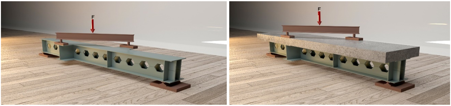
Figure 2. Specimens under Combined Load

Figure 3. Some Main Parameters in a Zigzag Pattern(10,11,12)

Where:
L: Length of the span (1560 mm).
d: The depth of the built-up section (150 mm).
D: Total depth of steel beam after castellation.
hp: Throat depth (The overall depth of the tee part connecting the web to the flanges).
e: Web Post (The part of the body that is limited or is placed between two holes).
S: The distance between the centers of the openings.
Castellation Ratio (λ): It is the change in depth to the original depth.
Expansion Ratio (ѱ): It is the proportion of manufactured or castellated beam depth to original (built-up) beam depth.
hₒ: high of the opening. n: No. of cells.
|
Table 1. Specifications and dimensions of the tested samples |
||||||||
|
Identification |
Dimension of parameters (mm) |
|||||||
|
bc |
tc |
e |
hₒ |
hp |
s |
ѱ |
D |
|
|
SB-1 |
0 |
0 |
0 |
0 |
0 |
0 |
1 |
150 |
|
CB-1,25 |
0 |
0 |
43,3 |
75 |
56,25 |
129,9 |
1,25 |
187,5 |
|
CB-1,5 |
0 |
0 |
86,6 |
150 |
37,5 |
259,8 |
1,5 |
225 |
|
CSB-1 |
350 |
80 |
0 |
0 |
0 |
0 |
1 |
150 |
|
CCB-1,25 |
350 |
80 |
43,3 |
75 |
56,25 |
129,9 |
1,25 |
187,5 |
|
CCB-1,5 |
350 |
80 |
86,6 |
150 |
37,5 |
259,8 |
1,5 |
225 |

Figure 4. Specimens under combined load
Material Properties
Properties of Built-up Steel Section
Specimens constructed from steel plates were manufactured in Isfahan. A CNC machine was used to cut three tension coupons from the web (4 mm) and flange (6 mm). These coupons were tested to all ASTM standards (A 370-05)(13) in order to find out how these steel pieces perform mechanically (yield stress, ultimate strength). The coupons were put through their paces at the Civil Engineering Department's Material Laboratory at Qadisiyah University. Test results are listed in table 2.
|
Table 2. Test Results of plate-section Steel |
|||
|
Plate Thickness (mm) |
Specimen No. |
Yield stress MPa (Fy) |
Ultimate stress MPa (Fu) |
|
4 |
Average of 3 NO |
337 |
400 |
|
6 |
Average of 3 NO |
428 |
455 |
Steel Bar
Experimental work included the use of steel reinforcement. The diameter was determined using the standards set out in ASTM A615 M-03a.(14) Table 3 shows the mechanical parameters of the steel bars. Tthe College of Engineering's laboratory at the University of Qadisiyah conducted these tests.
|
Table 3. Mechanical properties of reinforcement bar used |
||||
|
Nominal diameter of bar (mm) |
Weight of steel bar (kg/m) |
Equivalent steel bar diameter (mm) |
Tensile stress (Fy) (MPa |
Ultimate Tensile strength (Fu) (MPa) |
|
8 |
0,395 |
7,96 |
610 |
720 |
Cement
The study employed Al-Jesser, a type of ordinary Portland cement manufactured in Iraq, for the casting of all the concrete specimens. This is in accordance with the specifications outlined in ISS No. 5-1984.(14) The testing was conducted at the Laboratory of the Engineering College at Al-Qadisiyah University.
|
Table 4. Mechanical Properties of Cement |
||
|
Mechanical properties |
Test results |
IQ.S No. 5/1984 |
|
Fineness (blain method) (m^2 / kg) |
280 |
>230 |
|
Setting time initial (min) |
1:15 4:10 |
>45 (min) <(10) (hrs) |
|
Compressive strength, MPa 3day 7 day |
17 27 |
>15 N/(mm^2) >23 N/(mm^2) |
Fine Aggregate
The present study employed natural sand sourced from Karbala for the purposes of investigation. The test results indicate that the grading and sulfate content of the material meet the requirements outlined in Iraqi specification No. 45/1984, specifically in zone (2).(15) The experiments were conducted at the Laboratory of Engineering College, Al-Qadisiyah University.
|
Table 5. Mechanical and Chemical Properties of Fine Aggregate |
||
|
Properties |
Test results |
IQ.S No. 45/1984 zone (2) |
|
Fineness modulus |
2.64 |
---------- |
|
Sulphate content SO3 |
0,15 % |
≤ 0,5 % |
|
Specific gravity |
2,61 |
---------- |
|
Absorption |
0,77 % |
---------- |
Coarse Aggregate
The present study utilized natural gravel sourced from Al-Nibaey with a maximum particle size of 10 mm, specifically gravel with crushed surfaces. The course aggregate underwent multiple cleaning and washing cycles before being left to dry in ambient air. The duplication of the specified limits was tested and confirmed according to IS No. 45-1984.(16) The aforementioned tests were conducted in the laboratory of the Engineering College at Al Qadisiyah University.
|
Table 6. Mechanical and Chemical Properties of Coarse Aggregate |
||
|
Properties |
Test results |
IQ.S No. 45/1984 |
|
Clay content |
0,3 % |
≤ 2 % |
|
Sulphate content SO3 |
0,03 % |
≤ 0,1 % |
|
Specific gravity |
2,61 |
---------- |
|
Absorption |
0,7 % |
---------- |
Concrete Mix Design
To achieve a compressive strength of concrete (fc: 35 MPa), a standard concrete mixture was developed in accordance with BS using the ACI code (ACI 211.1-1991).(17) The results of a fresh mix test are shown in table 7.
|
Table 7. Mix Proportion of Concrete |
|
|
Materials |
Proportions (kg/m3) |
|
Cement |
400 |
|
Corse aggregate |
1150 |
|
Fine aggregate |
700 |
|
Water |
180 |
|
W/C ratio |
0,45 |
Beam testing, and dial gauge
As shown in figure 5, all specimens are tested using a two-point load that is applied outside of an airplane that is supported by a girder (i.e., eccentricity from the girder's midpoint), causing bending and torsion moments. In this loading test for both composite and non-composite sections, a metal beam arm is made of the same materials as a metal beam girder and welded on the factor load to prevent local slab collapse and transmit stresses to the metal beam. Look at Figure 6.The Structural Laboratory of Civil Engineering at the University of Qadisiyah conducted an experiment involving six supported, built-up castellated beams. These beams were subjected to testing using a hydraulic testing machine with a capacity of 1 500 kN. The experiment involved applying two equally focused monotonic loads to the beams until failure occurred. Dial gauges were employed to quantify the deflection at various locations, including the mid-span, the third point, and the arms, while incrementally increasing the load at intervals of 10 kN. At the locations corresponding to the third-span points, two identical and symmetrically concentrated loads were present. In order to maintain simplicity, the supports were designed to mirror this condition. Subsequently, following the application of the load and the measurement of the self-weight, the initial deflection readings were obtained, with subsequent data points recorded at intervals of 10 kN for deflection.

Figure 5. Load Methods and Dial Gauges
RESULTS AND DISCUSSIONS
The objective of this study was to examine the structural performance, load-bearing capacity, and failure modes of castellated steel beams that are both composite and non-composite in nature. In order to accomplish this objective, an assessment was conducted on six constructed double-web steel beams, with a specific emphasis on the castellation ratio and composite action as a crucial characteristic.The beams were subjected to testing or estimation at the midpoint of their span and while under load in order to ascertain their maximum strength, flexural and torsional moments, failure mechanism, load-to-deflection relationship, ductility ratios, and stiffness.
Behavior of tested non-composite castellated beams under combined load
Three simply supported, double web built-up steel beams with a span of 1 560 mm were brought down by combined bending and twisting forces. Three specimens are available: a solid beam with no castellated ratio (SB-FT 1), a castellated beam with a 25 % castellated ratio (CB-FT 1,25), and a castellated beam with a 50 % castellated ratio (CB-FT 1,5). Each aspect of steel beam load deflection has been meticulously documented. The bending and torsion moments listed below have been computed as a result: figure 6, with the abbreviations SB-FT1, CB-FT1,25, and CB-FT1,5, respectively, depict the deflected forms that were present throughout the steel beam's span. Web buckling, local buckling, and out-of-plane deformation were discovered to be the mechanisms of failure in non-composite-built-up double-web castellated steel beams.

Figure 6. Failure of specimens under combined (FT)
The deflections at midspan and under arm load for each specimen were measured at each loading increment. The load-deflection relationship for the specimens (SB-FT1, CB-FT1. 25, and CB-FT1. 5) is shown in figure 7.

Figure 7. Load-deflection relationships of non-composite specimens under combined (FT)

Where:
Pj = ultimate load (total jacking load at failure), (kN).
P = ultimate load at the third point, (kN).
M = bending moment at failure, (kN.m).
T = torsional moment at failure, (kN.m).
e = eccentricity of load at specimens that loaded out of supported plane (175 mm).
|
Table 8. Load at ultimate stages and midspan deflection of Specimens under continued Load (FT) |
|||||||
|
Specimen |
Weight (kg) |
Ultimate Load (kN) |
Difference (%) |
Bending* Moment (kN.m) |
Torsional* Moment (kN.m) |
Mid Def (mm) |
Difference (%) |
|
SB-FT 1 |
54 |
180 |
control |
46,8 |
15,75 |
9,5 |
control |
|
CB-FT 1,25 |
53 |
150 |
-17 |
39 |
13,12 |
8,9 |
-6,4 |
|
CB-FT 1. 5 |
53 |
135 |
-25 |
35,1 |
11,8 |
8,4 |
-11,5 |
Equation 8,9
Difference=(d2-d1)/d1
Table 8 demonstrates that the midspan of the beam is the non-composite specimens' ultimate level when bending and torsional moments are estimated using Equation above. Utilising the load-deflection curves depicted above, it can be observed that the relationship between load and deflection is predominantly linear until the yield load is reached. Subsequently, the connection becomes nonlinear, indicating that the specimen undergoes inelastic deformation until failure occurs. According to the data presented in Table 5, the ultimate load of a built-up castellated beam (CB-FT1,25 and CB-FT1,5) exhibits a reduction of 17 % and 25 %, respectively, when compared to the ultimate load of a built-up steel beam (SB-FT1). The presence of apertures in the double web led to a decline in both the ultimate strength and deflection as the castellation ratio of the web increased. Specifically, the drop in ultimate strength and deflection was found to be 6,4 % and 11,5 % for castellation ratios of 25 % and 50 %, respectively. The failure of (SB-FT1) can be attributed to buckling, which occurred at an ultimate load of 180 kN. It is noteworthy that the beams (CB-FT 1,25 and CB-FT1,5) were equipped with hexagonal apertures on their shear panels. The failure occurred at load values of 150 kN and 135 kN, respectively, as a result of web buckling between the perforations under maximum stress conditions.
Figure 6 illustrates the failure mechanism observed in the tested SB-FT1, CB-FT 1,25 and CB-FT1,5 built-up steel plate beams. The observed phenomena include alterations in the form, buckling of the diagonal web, and failure of the top lip of the specimen at the loading arm. These occurrences were consistent across all specimens when subjected to the maximum load. All specimens exhibited a common failure mode, characterised by initial elastic behaviour of the built-up steel plate beam, accompanied by diagonal web bending observed in nearly all web panels. As the applied load increased, the structural integrity of the top lip on the loading arm became compromised, resulting in its deformation and subsequent failure.
Behavior of tested composite castellated beams under combined load
Three double web built-up steel beams with a span of 1560 mm were tested under combined flexural and torsional stresses to failure. The three composite specimens, namely the solid (0 %) castellated beam (CSB-FT 1), the 25 % castellated beam (CCB-FT 1,25), and the 50 % castellated beam (CCB-FT 1,5), denoted as CSB-FT1, CCB-FT1,25, and CCB-FT1,5, respectively, exhibit the deflected configurations observed along the whole span of the steel beam. The failure mechanisms seen in composite-built-up double-web castellated steel beams were identified as longitudinal cracks, diagonal cracks, and local failure.

Figure 8. Failure of composite specimens under combined (FT)
For each specimen, deflections were measured at the midspan and under load (third span) for each loading increment. In figure, we see the load-deflection relationship for specimens (CSB-FT1), (CCB-FT1,25), and (CCB-FT1,5). Table 9 displays the load, flexural and torsional moments, and midspan deflection for composite specimens in the final stage.

Figure 9. Load-deflection relationships of composite specimens under combined (FT)
|
Table 9. Load at ultimate stages and midspan deflection of composite Specimens under continued Load |
|||||||
|
Specimen |
Weight (kg) |
Pj (kN) |
Difference (%) |
M (kN.m) |
T (kN.m)* |
Mid Def (mm) |
Difference (%) |
|
CSB-FT 1 |
172 |
290 |
control |
79,75 |
25,37 |
9 |
control |
|
CCB-FT 1,25 |
171 |
245 |
-15,5 |
67,3 |
21,4 |
6,53 |
-27,4 |
|
CCB-FT 1. 5 |
171 |
210 |
-27,5 |
57,75 |
18,37 |
6,92 |
-23,1 |
Equation 8,9
Difference=(d2-d1)/d1
From the load-deflection curves depicted above, it is evident that the correlation between load and deflection is predominantly linear until the yield load is reached. Subsequently, the relationship becomes nonlinear, indicating the occurrence of inelastic deformation. This is accompanied by a decrease in the slope of the load-deflection relationship of the specimen, ultimately leading to failure. The composite built-up castellated steel beams, specifically CCB-FT1,25 and CCB-FT1,5, exhibit a reduced ultimate load when compared to composite built-up solid steel beams (CSB-FT1) by proportions of 15,5 % and 27,5 %, correspondingly. The presence of apertures in the double web led to a reduction in the ultimate strength and deflection of the structure as the castellation ratio in the web grew. Specifically, the ultimate strength decreased by a factor of 27,4 % and the deflection decreased by a factor of 23,1 % for castellation ratios of 25 % and 50 %, respectively. The failure mechanism is identified by the appearance of diagonal cracks on the top surface of the concrete deck slab. These fractures arise when the load threshold that triggers cracking is reached. The presence of these fractures can be ascribed to the tensile stress generated by a torsional moment, particularly at the locations of the concentrated loads. As the magnitude of stress escalates, there is an augmented prevalence of longitudinal fractures at shear connections, accompanied by an elevated incidence of diagonal cracks. In conclusion, it is important to highlight that the possible failure of a composite girder depends on the stiffness of the web. This failure might manifest in two ways: either through the failure of the concrete deck slab or through the buckling and subsequent collapse of the web.The ductility ratio and initial stiffness of the tested materials were determined from the retrieved data. Table 10(18)
|
Table 10. Stiffness values, and ductility ratio of the tested specimens |
|||
|
Group specimen |
Specimen |
Ki initial stiffness |
Ductility Ratio |
|
Non-composite |
SB-FT 1 |
38,60 |
1,93 |
|
CB-FT 1,25 |
37,50 |
2,54 |
|
|
CB-FT 1. 5 |
35,63 |
2,96 |
|
|
Composite |
CSB-FT 1 |
53,32 |
1,53 |
|
CCB-FT 1,25 |
50,08 |
1,86 |
|
|
CCB-FT 1,5 |
44,08 |
1,94 |
|
Effect of Composite Action
The experimental study involved testing both composite and non-composite built-up castellated steel beams under combined flexural and torsional loading conditions. This examination aimed to get insights into the influence of concrete slabs in composite sections on the ultimate load capacity.
Figure 10 depict the load-deflection relationship between composite and non-composite specimens with varying castellation ratios, while table 11 demonstrates the influence of concrete slab on composite castellated beam behavior.

Figure 10. The effect of composite action on the behavior of beam under combined load
|
Table 11. The effect of a deck slab on composite specimens under combined load |
||||||
|
Specimen |
Ultimate load (kN) |
Difference (%)* |
Ki stiffness (kN/mm( |
Difference (%)* |
Ductility Ratio |
Difference (%)* |
|
SB-FT 1 |
180 |
ــــ |
38,60 |
ــــ |
1,93 |
ــــ |
|
CSB-FT 1 |
290 |
61,1 |
52,32 |
35,5 |
1,53 |
-20,7 |
|
CB-FT 1,25 |
150 |
ــــ |
37,50 |
ــــ |
2,54 |
ــــ |
|
CCB-FT 1,25 |
245 |
63,3 |
50,08 |
33,5 |
1,86 |
-26,7 |
|
CB-FT 1. 5 |
135 |
ــــ |
35,63 |
ــــ |
2,96 |
ــــ |
|
CCB-FT 1. 5 |
210 |
55,5 |
43,08 |
20,9 |
1,94 |
-34,5 |
According to the empirical results, it has been shown that the inclusion of a concrete slab leads to a significant enhancement in the ultimate load capacity. Specifically, the ultimate load is augmented by about 61,1 %, 63,3 %, and 55,5 % for castellation ratios of 0 %, 25 %, and 50 % respectively. Moreover, the addition of the concrete slab results in an increase in stiffness and a loss in ductility for specimens subjected to combined loading conditions. Additionally, it has been shown that the composite castellated samples exhibit an augmented stiffness and reduced deflection as a result of the influence of concrete, in contrast to the non-composite castellated samples. Based on the aforementioned observations, it can be inferred that composite castellated beams exhibit a higher ultimate load capacity and reduced deflection, whereas non-composite components have a lower ultimate load capacity accompanied by increased deflection. Furthermore, it was noted that the presence of a concrete slab in the composite section not only enhances the strength capacity of the built-up steel plate beam, but also provides restraint to the compression flange, preventing it from warping under torsional forces. Simultaneously, the concrete slab allows the tension flange to freely warp in response to the torsional effect.
The superiority of the composite over the non-composite was established due to the concrete slab's ability to modify the geometrical parameters of the cross section, including the placement of the neutral axis, moment of inertia, stiffness, stress distribution, and other factors.
Effect of Castellated Ratio
The load deflection relationship between different castellated ratios is elucidated in (figure 11) in the experimental study. Table 2 presents the impact of the castellated ratio on composite castellated steel beams, as derived from empirical testing data.

Figure 11. The effect of castellated ratio on the behavior of specimens under
|
Table 12. Effect of Castellated Ratio |
||||||
|
Specimen |
Ultimate load (kN) |
Difference (%)* |
Ki stiffness (kN/mm( |
Difference (%)* |
Ductility Ratio |
Difference (%)* |
|
Non-composite |
||||||
|
SB-FT 1 |
180 |
ــــ |
38,60 |
ــــ |
1,93 |
ــــ |
|
CB-FT 1,25 |
150 |
-16,6 |
37,50 |
-2,8 |
2,54 |
31,6 |
|
CB-FT 1. 5 |
135 |
-25 |
35,63 |
-7 |
2,96 |
53,3 |
|
Composite |
||||||
|
CSB-FT 1 |
290 |
control |
53,32 |
ــــ |
1,53 |
ــــ |
|
CCB-FT 1,25 |
245 |
-15,5 |
50,08 |
-6 |
1,86 |
21,5 |
|
CCB-FT 1,5 |
210 |
-27,5 |
44,08 |
-17,3 |
1,94 |
26,7 |
Based on the final load data, it was observed that the shear strength of both non-composite and composite castellated beams exhibited a reduction with an increase in the expansion ratio. The ultimate load reduction percentages for non-composite beams at the failure stage are 16 % and 25 % for castellation percentages of 25 % and 50 %, respectively. Similarly, the ultimate load reduction percentages for composite castellated beams at the same level are 15,5 % and 27,5 % for castellation percentages of 25 % and 50 %. Simultaneously, a reduction in the rigidity of both non-composite and composite samples is observed as the castellation ratio in the double web increases. This decrease is attributed to the effects of flexural and torsional forces, resulting in stiffness reductions of 2,8 % and 7 % for flexural loading, and 6 % and 17 % for torsional loading, respectively. The additional load imposed on the samples in this group, specifically flexural and torsional forces, contributes to the observed decrease in stiffness. Moreover, it is noteworthy that these specimens are regarded as possessing a significant degree of ductility.
CONCLUSIONS
Based on the results achieved from the experimental work, the main conclusions can be drawn as:
1. The enhanced ultimate strength of the composite section is attributed to the contribution of the reinforced concrete slab when subjected to coupled flexural and torsion stresses in a composite steel beam.
2. The concrete slab demonstrates an increase in the ultimate load, with respective rates of 61,1 %, 63,3 %, and 55,5 %, for castellation ratios of 0 %, 25 %, and 50 %.
3. The specimens subjected to a combined load exhibit an increase in stiffness and a decrease in ductility. Additionally, it has been shown that the composite castellated samples exhibit an enhanced stiffness and reduced deflection as a result of the influence of concrete,
4. The shear strength of both non-composite and composite castellated beams exhibited a reduction as the expansion ratio increased.
REFERENCES
1. Knowles, P. and B.J.P.o.t.I.o.C. Engineers, CASTELLATED BEAMS. 1991. 90(3): p. 521-536. Available from: http://www.johnmartin.com/castellated-beams-at-emerson-collegelos-
2. Megharief, J., Behavior of composite castellated beams, 1997. Partial M. Sc. 1997, thesis. McGill University, 1997.[14] Kloeckner Metals UK, No Title,(nd ….
3. Larnach, J., R.J.C.E. Park, and P.W. Review, The behavior under load of six castellated composite T-beams. 1964. 59(692): p. 339-343.
4. Abbas, A.M.J.A.-Q.J.f.E.S., Numerical Investigation on the Influence of Web Opening on the Structural Behaviour of RC Deep Beams. 2019. 12(3).
5. Hartono, W. and S. Chiew. Composite behaviour of half castellated beam with concrete top slab. in Proceedings: International Conference on Advances in Steel Structures. 1996. Pergamon New York.
6. Oukaili, N.K. and S.S. Abdullah. Behavior of Composite Concrete-Castellated Steel Beams under Combined Flexure and Torsion. in APFIS2017-6th Asia-Pacific Conference on FRP in Structures. 2017.
7. Al-Khekany, A.M. and H.H.J.A.-Q.J.f.E.S. Muteb, Effect of composite action of concrete slab on unsymmetrical steel plate girder under combined bending and torsion moments. 2017. 10(3): p. 338-351.
8. Al-Faten, S.A. and A.M. Al-Khekany. Effect of composite action on castellated steel beam under combined bending and torsion moments. in AIP Conference Proceedings. 2023. AIP Publishing.
9. Construction, A.I.o.S., Load & Resistance Factor Design: Connections. Vol. 2. 1994: American Institute of Steel Construction.
10. Abdulridha, S.Q., H.H. Muteb, and S.S.J.J.o.U.o.B.f.E.S. Abdulqader, Structural Behavior of Composite Castellated Steel Concrete Beams Subjected to Impact Load. 2018. 26(8): p. 1-12.
11. Demirdjian, S., Stability of castellated beam webs. 1999.
12. Al-Thabhawee, H.W. and A.A.J.A.-Q.J.f.E.S. Mohammed, Reinforcing the octagonal Web openings of castellated beam by steel rings. 2019. 12(1): p. 7-16.
13. ASTM, A.J.A., Philadelphia, PA, 370-05," Standard Test Method and Definition for Mechanical Testing of Steel Products", Annual Book of ASTM Standard, Vol. 01.01. 2005.
14. Bars, A.R., ASTM A 615/A 615M. Grade.
15. Specification, I.S.J.C.O.f.S. and B. Quality Control , Iraq, No. 5/1984, portland cement. 1984.
16. No, I.S.J.B., Iraq, for Aggregates of Natural Resources used for Concrete and Construction. 1984.
17. Siswanto, E., PEMBANGUNAN APLIKASI MOBILE PERANCANGAN MIX DESIGN BETON NORMAL BERDASARKAN METODE ACI 211.1-1991 BERBASIS ANDROID. 2015, UAJY.
18. Vu, N.S., B. Li, and K.J.E.S. Beyer, Effective stiffness of reinforced concrete coupling beams. 2014. 76: p. 371-382.
FINANCING
The authors did not receive financing for the development of this research.
CONFLICT OF INTEREST
The authors declare that there is no conflict of interest.
AUTHORSHIP CONTRIBUTION
Conceptualization: Farroq A .Abass, Alaa M. Al-Khekany.
Data curation: Farroq A .Abass, Alaa M. Al-Khekany.
Formal analysis: Farroq A .Abass, Alaa M. Al-Khekany.
Research: Farroq A .Abass, Alaa M. Al-Khekany.
Methodology: Farroq A .Abass, Alaa M. Al-Khekany.
Drafting - original draft: Farroq A .Abass, Alaa M. Al-Khekany.
Writing - proofreading and editing: Farroq A .Abass, Alaa M. Al-Khekany.