doi: 10.56294/sctconf2024848
Category: STEM (Science, Technology, Engineering and Mathematics)
ORIGINAL
Numerical Simulation of Forming a 3D Shape by a Multi-Point Die Simulación
Numérica del conformado de una forma tridimensional mediante una matriz multipunto
Alyaa Al-Ghuraibawi1 *, Aseel Hamad Abed1 *, Khalida Kadhim Mansor1 *
1Department of Production Engineering and Metallurgy, The University of Technology. Iraq.
Cite as: Ghuraibawi AA, Abed AH, Mansor KK. Numerical Simulation of Forming a 3D Shape by a Multi-Point Die. Salud, Ciencia y Tecnología - Serie de Conferencias. 2024; 3:848. https://doi.org/10.56294/sctconf2024848
Submitted: 28-01-2024 Revised: 13-04-2024 Accepted: 07-06-2024 Published: 08-06-2024
Editor: Dr.
William Castillo-González ![]()
Note: Paper presented at the 3rd Annual International Conference on Information & Sciences (AICIS’23).
ABSTRACT
Multi-point forming (MPF) is considered one of the flexible and creative three-dimensional sheet metal forming processes. Such a technique replaces traditional rigid punches with a set of adjustable-height discrete pins. By altering the relative height of each pin, a variety of three-dimensional curved surfaces can be formed. In order to avoid changing the height of the pins manually, they are attached to springs. Hence, when a load applies at the pins holder, these will take the shape of the die due to the spring properties quickly and easily. However, wrinkles and dimples are inevitable issues that appear when using MPF. In order to investigate and minimize these defects, a finite element approach using ANSYS 15.0 software has been applied to perform numerical simulations for this MPF operation. Two cases have been examined in this study. Whilst the first one includes direct forming between the pins and the metal, a sheet of rubber has been added among them in the second case. The simulation has been conducted on brass (Cu Zn 65-35) with a thickness of (0,71 mm) and rubber with a thickness of (2 mm). The boundary conditions, which are attached to the blank, enable the motion in the y-direction only with respect to the lower profile at a depth of (30) mm, and was immobilized by constraints in the x and z direction. The study has shown remarkable results since the dimples were visible on the sheet surface in the first case, whereas these defects were significantly reduced during the second one. Moreover, the blank profile’s maximum stress and strain have been studied. Due to force distribution, rubber reduces maximum stress and strain to approximately 27 % and 49 %, respectively, in the second case.
Keywords: Multi-Point Forming; Multi-Point Die; Sheet Metal Forming; Numerical Simulation.
RESUMEN
El conformado multipunto (MPF) se considera uno de los procesos flexibles y creativos de conformado tridimensional de chapa metálica. Esta técnica sustituye los punzones rígidos tradicionales por un conjunto de pasadores discretos de altura ajustable. Alterando la altura relativa de cada pasador, pueden formarse diversas superficies curvas tridimensionales. Para evitar cambiar manualmente la altura de las clavijas, éstas están sujetas a muelles. De este modo, cuando se aplica una carga en el soporte de los pasadores, éstos adoptarán la forma de la matriz debido a las propiedades del muelle de forma rápida y sencilla. Sin embargo, las arrugas y los hoyuelos son problemas inevitables que aparecen al utilizar MPF. Con el fin de investigar y minimizar estos defectos, se ha aplicado un enfoque de elementos finitos utilizando el software ANSYS 15.0 para realizar simulaciones numéricas de esta operación MPF. En este estudio se han examinado dos casos. Mientras que el primero incluye la conformación directa entre los pasadores y el metal, en el segundo caso se ha añadido una lámina de caucho entre ellos. La simulación se ha realizado en latón (Cu Zn 65-35) con un espesor de (0,71 mm) y caucho con un espesor de (2 mm). Las condiciones de contorno, que se fijan a la pieza en bruto, permiten el movimiento en la dirección y sólo con respecto al perfil inferior a una profundidad de (30) mm, y se inmovilizó mediante restricciones en la dirección x y z. El estudio ha mostrado resultados notables, ya que los hoyuelos eran visibles en la superficie de la chapa en el primer caso, mientras que estos defectos se redujeron significativamente en el segundo. Además, se han estudiado las tensiones y deformaciones máximas del perfil de la chapa. Debido a la distribución de fuerzas, el caucho reduce la tensión y la deformación máximas hasta aproximadamente un 27 % y un 49 %, respectivamente, en el segundo caso.
Palabras clave: Conformado Multipunto; Matriz Multipunto; Conformado De Chapa; Simulación Numérica.
INTRODUCTION
One of the most common sheet metal forming techniques is the bending process, which can be accomplished in various ways. This includes forming along the whole bend in a die, wiping, folding, flanging the sheet in specialized equipment, or sliding the sheet over a radius in a die.(1) Depending on the complexity and size of the design, the manufacturing of traditional sheet forming equipment is difficult, costly, and requires a large storage space, and hence, it is only practical in the case of mass production.(2) In the past few decades, many advanced sheet metal forming technologies with more adaptable processes and tools have been suggested and developed. This is to meet the demand for low-cost, low-volume, or high-efficiency production. The most interesting of these techniques are multi-point process technology, sheet hydroforming, and incremental sheet forming.(3,4) Among these techniques, the multi-point formation (MPF) possesses significant characteristics as well as a wide array of capabilities. In this field of research, studying such a technique presents a considerable challenge.
MPF is a flexible process for manufacturing sheet metal products. The concept is based on assembling a set of pins in the same size and shape into a square, rectangular, or even a circular array. Then, the height of the pins are reconfigured to make the desired shape.(5,6) Such a process can be utilized to form various curved surfaces without the requirement for manufacturing several dies.(7) Figure 1 a and b illustrates the forming process in the initial and final stages, respectively.

Figure 1. Process of multi-point flexible formation
This paper presents a numerical simulation of a MPF process for the purpose of producing a complex surface. Firstly, a fin shape is designed based on a Bezier surface equation via MATLAB software. Then, a multi-point punch and curvature die were drawn in a SOLIDWORKS package. In order to reduce the time of changing the height of the pins manually, these have been attached to springs. A numerical simulation has been achieved using ANSYS 15.0 software to confirm the capability of this approach. Finally, a piece of rubber has been added between the multi-point punch and the workpiece to avoid or minimize wrinkles and dimples.
Previous work
The concept of flexible multipoint forming has been widely used in different industries, such as aerospace and marine.(8) To date, much research and many publications have been devoted to developing MPF systems. Some of previous MPF techniques and approaches are presented in this section. V. Paunoiu et al.(9) (2008) investigated the effect of the pin’s section on the deformation process in a reconfigurable multi-point forming (RMF) with a fixed configuration using finite element simulation of sheet metal forming. Differ factors, such as thickness, stresses, strains, and spring back differences were used to evaluate the deformation. The simulation modeled the punch and die twice. Each network has been created with a specific shape of pin’s section. Whilst the first network instrument includes circular pins, each pin of the second one has a square section. Since the stresses, total force, and spring back are identical, this means that both the circular and square pins produce a similar deformation. Thus, conceptual factors must determine which network to use. L. Li, et al.(10) (2010) proposed a dynamic explicit and static implicit finite element method to control and reduce the spring back phenomenon. Firstly, different factors such as the thickness of the sheets, deformation amount, and material properties have been investigated to study their influence on the spring back. Next, a multi-step MPF concept has been suggested for the purpose of decreasing the spring back amount. According to the authors, the multi-step MPF approach does not only reduce the spring back for it also improves the workpiece stress state. Finally, the numerical simulation results have been confirmed via an experimental work.V. Xue Zhi, et al.(11) (2014) presented numerical simulation with an aluminum alloy and a hollow profile using finite element analysis (FEA) software. The main objective is to study the possibility of avoiding the inevitable dimples that always occur when using the MPF technique with profile forming. The simulation has been conducted many times with different sizes of punch elements and kind of elastic cushion. The best outcome of such a process was gained while using a punch element size with 15mm×15mm and applying a spring steel plate with 1mm thickness as a cushion. Furthermore, the multi-step technique can be combined with the MPF process to bend hollow profiles under smaller radii.
R. Wardhani, et al.(5) (2014) created a hexagonal arrangement of the pins with the MPF technique to investigate numerically the effects of the suggested arrangement of the pins versus the specified square packing as shown in Figure 2. It takes merely a glance to notice that the density of the hexagonal arrangement is higher than the square one. The numerical simulation of the MPF hexagonal packing gives more effective results in comparison with the square packing in terms of stress and strains distribution. However, the high dense of pins can negatively affect on the blank sheet since more dimples are formed at the finished product.

Figure 2. Pins configuration in hexagonal packing and square packing(5)
M. Manea, et al.(12) (2014) used Deform 3D software to simulate the process of multi-point die optimization and sheet metal deformation. The simulation has been performed for both hot and cold plastic deformation processes with four different materials (grade 1 titanium, 2024 aluminum, 1010 and 1137 carbon steel). This is to analyze the behavior of each material and study the difference between the tension and deformation occurred during the MPF process. Furthermore, the software can report rich information regarding the stress strain metrics, distribution of temperature, Y-axis displacement, defects on the materials, and deformed surface analyses. Studying these results can help in reducing the amount of material damage caused by deformation, and hence, improve the quality of the products made by MPF processes.
Different MPF strategies have been developed over the years to consider the necessary factors of the process. Some researchers gave great emphasis on converting the manually adjusting of the pins to an automated one, since the former consumes time and effort, and might give un accurate results. On the other hand, studying various types of defects and material behavior during and after completing the process helped in diagnosing issues and suggesting solutions. For example, it is possible to avoid or reduce the dimples on the surface either by changing the pins arrangement or adding an elastic cushion. Also, the inevitable phenomena of spring back is shaping a vital area of research and many specialists have been working on it to find significant solutions. Since the concept of MPF plays an important role in the manufacturing industry, this requires further investigation in order to cover and optimize its essential aspects.
Geometry algorithm
The MPF technique can be used to create a variety of simple or complex shapes. The target shape of this study is a challenge application since it represents a free form surface. It has been selected based on an existing propel seven fins fan. Figure 3 a and b shows an individual fin and a whole assembled fan, respectively. The concept of reverse engineering has been used to extract the product’s measurements and dimensions. This is accomplished using the Bezier surface equation via MATLAB software which is often represented using the following equation:

Where:
B(u, v) is the Bezier surface.
(u, v) are the parameters.
n, m are the degrees of the surface in the u and v directions.
Bi,j (u, v) are the Bernstein basis functions.
Pi,j are the control points.

Figure 3. (a) A single fin and (b) a fully completed fan
This equation allows for the definition of complex curved surfaces in computer graphics, and it involves modifying the control points until a match is found between the surface meshes and the desired form. Figure 4 a, b, and c shows the final surface mesh with and without control points in MATLAB program. Furthermore, a part of the MATLAB program that uses the cubic Bezier surface equation is shown in Appendix.

Figure 4. (a) The generated MATLAB surface mesh with control points, (b) and (c) the generated MATLAB surface mesh without control points, shown in different views
The next step includes generating a cloud of points that represent the required surface. This cloud is exported to the SOLIDWORKS environment for the purpose of creating a 3D surface model. Also, it can be used to draw the lower profile die, which is illustrated in figure 5.

Figure 5. A SOLIDWORKS die design
The multi-point die
The sheet metal forming processes are widely used in the fabrication and manufacturing of parts and components. Although they serve the same objective, each is developed based on a different concept and has its own set of instruments and tools. Regarding the proposed flexible multi-point die (MPD), this section presents a whole description of the parts and their role in achieving the forming process. In contrast with the traditional forming concept of punch and die, the MPD replaces the one piece of punch with a set of 121 adjustable pins. The set of adjustable pins helps in forming different shapes, and hence there is no need to fabricate a new punch for each product. Each pin has a square section of 15 mm and a hemispherical shape of 7,5 mm radius at the bottom end, whereas the top end has a threaded hole with 8 mm diameter and 40 mm depth. Also, a cylindrical ring of 2 mm height and 5 mm radius is designed at the top end to restrict the movement of the spring. The high-carbon steel has been selected for the pins. Figure 6 shows a front section of the designed pin.

Figure 6. A front section of the pin
In order to avoid the manual adjustment of the pins, each pin is attached to a spring via a bolt. The bolt is screwed from one end to the pin, whereas the other end is free and not connected to any part. Hence, the pin moves vertically whenever a load is applied due to the spring mechanism. The selected spring is 80 mm length and 6,5 mm radius. According to the compressioradiusn test’s load-deformation curve, the greatest load that can be applied to the spring is 236 N, which results a maximum displacement of 44 mm. Hence, the calculated value of the spring stiffness is 5,36 N/mm.
The 121 pins are grouped together in a square layout as 11*11 matrix via un upper block that is measured (280*280*15) mm. The block includes 121 holes with 4 mm in radius to attach the pins, as well as four holes at the corners for the purpose of adding guides. The guides are designed with 11 mm in radius and 270 mm in length. Finally, the lower block includes four holes at the corners with a radius of 11 mm. Figure 7 illustrates the assembly of the proposed MPD die.(2)

Figure 7. The whole MPD after assembly
Although replacing the one piece of punch with a set of adjustable pins eliminates the necessity of fabrication a specific punch for each product, this does not include the fabrication of the bottom die. The bottom die is designed individually and should be manufactured and assembled with the MPD each time if a different product is required. Assembling the MPD with the bottom die depends on some constraints. For example, the size and shape of the pins might affect on the position of the bottom die. Also, the size of the die should not exceed the effective forming area of the MPD. In contrast, a smaller size of die can be used, and hence, not all the pins will be activated during the forming process. Figure 8 shows the assembled MPD with that bottom die.

Figure 8. MPD in assembly with bottom die
Materials selection
One of the numerical simulation requirements is the selection of the product material, as well as the other effective parts. The brass alloy (Cu Zn 65-35) has been selected for the fin blank with a thickness of 0,71 mm. Figure 9 shows all the dimensions of the blank. Also, for the purpose of minimizing the dimpling caused by individual pins, a sheet of rubber with 84 HA hardness and 2 mm thickness has been applied during the simulation. Tables 1 and 2 summarized the mechanical properties of the brass plate that had been obtained by tensile tests and the rubber, respectively.

Figure 9. The top view of the blank with its dimensions
|
Table 1. Mechanical properties of the brass 65-35 plate |
|||||
|
Material |
Ultimate Strength [MPa] |
Young’s Modulus [GPa] |
Poisson’s Ratio |
Yield Stress [MPa] |
Tangent Modulus [MPa] |
|
Brass (65-35) |
U |
E |
υ |
σy |
Et |
|
230 |
110 |
0,355 |
79 |
39 |
|
|
Table 2. Mechanical properties for the used elastic layer (rubber) |
|||
|
Material |
Yield stress [MPa] |
Young’s Modulus [MPa] |
Poisson’s Ratio |
|
Rubber |
10 |
25 |
0,48 |
Numerical simulation
Since decades ago, computers have been used to assist in many tasks due to their ability to perform complex functions in a fast and accurate way. For example, they can analyze and examine the features and the characteristics of a product or process. Different approaches, techniques, and concepts have been developed for this matter, with the most recognized being FEA. FEA can be performed via various software; however, the ANSYS-PC is considered one of the most powerful choices.
MPF is a challenging mechanical operation that can be used with non-linear shapes and boundary conditions. This work utilizes the ANSYS 15.0 software to achieve the numerical simulation under specific considerations. For instance, the element type Brick 8 node 185 has been implied for the purpose of building explicit structural model and achieving computing efficiency. Also, due to its complexity and non-symmetry, the whole 3D model of the fin-shape is taken into consideration during the simulation process. Furthermore, in ANSYS it is customary to specify the mechanical properties of brass and rubber materials, including the hardness of the rubber, as outlined in the material selection section, in order to characterize them. In order to analyze the differences of the curvature between the target surface and the resulted one, a node displacement is used to simulate the movement of the upper pins. The boundary conditions, which are attached to the blank, enable the motion in the y-direction only at a depth of 30 mm, and fix the (x and z) axes. The simulation includes three zones of contact that should be defined. The first one is used to represent the interaction between the blank sheet and the rubber pad (surface to surface /flexible). Whereas the second contact has been defined for the elastic cushion’s interaction with the upper pins (surface to surface /rigid). Finally, a contact between the lower surface of the blank and the lower die (surface to surface /rigid). The friction coefficient value of the rubber and the blank has been selected as 0,02.
In order to evaluate the proposed solution’s ability in reducing the wrinkles and dimples issues, two case studies have been simulated. The first case includes direct contact between the upper pins, brass blank, and lower die. Whereas a sheet of rubber has been added between the upper pins and the blank at the second one. Figure 10 a and b illustrates the two case studies, respectively.

Figure 10. (a) Case study 1 (direct contact) and (b) case study 2 (with adding rubber)
RESULT AND DISCUSSION
As mentioned, this study presents a numerical simulation of an MPF process via two different cases: (i) direct contact and (ii) indirect contact using a sheet of rubber. This section introduces a discussion of the results based on stress and strain diagrams of the two cases. Figure 11 a and b represents the Von-Mises stress distribution on the formed metal sheet without and with adding the sheet of rubber, respectively. Whilst the maximum Von-Mises stress in the case of direct contact is 155 MPa, the maximum Von-Mises stress is less after adding the rubber 113 MPa. Also, the yellow zone that covers most of the formed surface in the second case is higher in comparison with the first one. This means that the use of rubber enhances the force distribution and allows the upper pins to press on the workpiece surface efficiently.
Regarding the strain distributions, Figure 12 a and b shows the two cases of direct and indirect contact, respectively. The zone of the tough thickness decrease in the case of direct contact is higher than the one with using rubber. Consequently, adding a rubber sheet enhances the strain distribution. It can even be noticed that the use of rubber improves the final forming results in terms of having smooth curvature edges of the product.

Figure 11. (a) The stress distribution of case study 1 and (b) the stress distribution case study 2
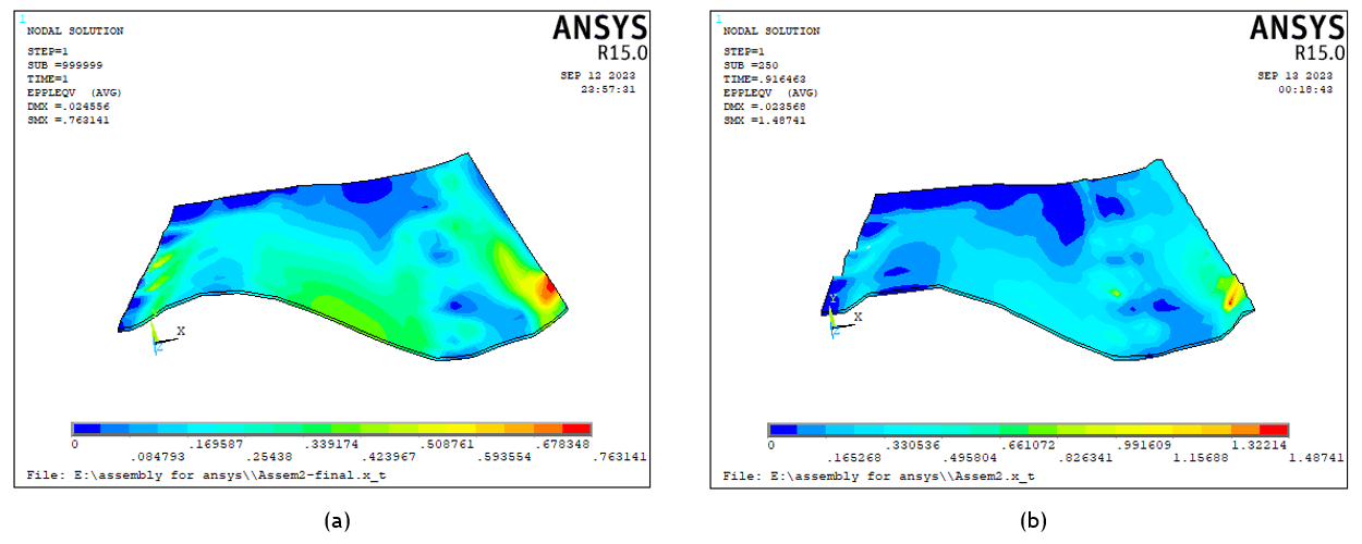
Figure 12. (a) The strain distribution of case study 1 and (b) the strain distribution case study 2
The most noticeable defects in the MPF processes are wrinkling and dimpling. It takes a mere glance to distinguish these phenomena in Figures 11a and 12a. The space between the active points of the pins increases the stress concentration at these points during the forming process and the dimples have a shape as same as the pins. However, the dimples do not occur at the same visibility at the formed surface. This is due to the complexity and non-symmetry of the 3D shape, which requires a different displacement for each pin to form the final shape. Whilst the accuracy of the curvature indicates the quality of the forming process, the poor quality is considered a sign of the wrinkling defect. This also can be noticed in figures 11a and 12a. Both wrinkling and dimpling have been significantly reduced after using the sheet of rubber.
CONCLUSION
MPF is one of the significant sheet metals forming methods that is used in different applications of industry since it can produce simple and complex shapes. In comparison with the traditional method, MPF replaces the upper one piece of punch with a set of adjustable pins, which are arranged in a specific layout based on the requirements. By adjusting the height of the pins in a way that allows them to touch the bottom die after applying pressure, they can form any shape. Such a technique eliminates the necessity of manufacturing a special punch for each product, and hence, reduces the manufacturing time and cost. However, there are still few cons that should be considered. For example, the manual adjustment of the pins might consume time and does not give accurate results. Also, the space and the shape of the pins can negatively affect the quality of the formed surface.
In this research, two different cases are simulated numerically using ANSYS 15.0 software. Whilst the first case is performed under direct contact between the mold’s parts and the workpiece, a sheet of rubber is added between the pins and the workpiece. The simulation of the first case shows obvious defects at the formed sheet in terms of dimpling, wrinkling, and the poor accuracy of the curvature edges. Adding a sheet of rubber does not only reduce the mentioned defects, for it also improves the final stress and strain distributions. In both cases, each pin is attached to the upper block via a guide and spring. Due to the elasticity of the springs, they help in achieving automatic adjustment of the pins, consequently the setup time is reduced up to 90 %.
REFERENCES
1. Z. Marciniak, J. L. Duncan, and S. J. Hu, Mechanics of sheet metal forming. Butterworth Heinemann, 2002.
2. T. F. Abbas, K. M. Younis, and K. K. Mansor, “The influence of process parameters on thickness distribution in multipoint forming process using finite element analysis.” Institute of Electrical and Electronics Engineers Inc., 2 2019, pp. 120–125.
3. Q. Zhang, Z. R. Wang, and T. A. Dean, “The mechanics of multi-point sandwich forming,” International Journal of Machine Tools and Manufacture, vol. 48, pp. 1495–1503, 10 2008.
4. W. Liu, Y. Z. Chen, Y. C. Xu, and S. J. Yuan, “Evaluation on dimpling and geometrical profile of curved surface shell by hydroforming with reconfigurable multipoint tool,” International Journal of Advanced Manufacturing Technology, vol. 86, pp. 2175–2185, 9 2016.
5. R. Wardhani, S. Putu, B. L. Sanjoto, H. Nur, and S. Hari, “Numerical simulation of multipoint forming with circular die pins in hexagonal packing,” vol. 493. Trans Tech Publications Ltd, 2014, pp. 589–593.
6. A. S. Bedan, S. J. Algodi, and E. A. Hussain, “Investigating the effect of hybrid process: Mpf/spif on the microstructure and mechanical properties of brass (65-35) sheet,” Advances in Science and Technology Research Journal, vol. 17, pp. 302–308, 2023.
7. Z. R. Qian, M. Z. Li, and F. X. Tan, “The analyse on the process of multi-point forming for dish head,” Journal of Materials Processing Technology, vol. 187-188, pp. 471–475, 6 2007.
8. H. Belhadjsalah, N. Selmi, and H. Belhadjsalah, “.flexible multipoint hydroforming using metallic sheet medium,” Deuxi`eme Congr`es Tunisien de M´ecanique, 2012. [Online]. Available: https://www.researchgate.net/publication/255962595
9. P. V., C. P., G. E., and N. D., “Numerical simulations in reconfigurable multipoint forming,” International Journal of Material Forming, pp. 181–182, 2008.
10. L. Li, Y. H. Seo, S. C. Heo, B. S. Kang, and J. Kim, “Numerical simulations on reducing the unloading springback with multi-step multi-point forming technology,” International Journal of Advanced Manufacturing Technology, vol. 48, pp. 45–61, 4 2010.
11. X. Z. Liu, C. G. Liu, Y. Yao, and X. G. Zhang, “Numerical analysis for multi-point forming of aluminum alloy profile,” vol. 1035. Trans Tech Publications Ltd, 2014, pp. 128–133.
12. M. C. Manea, D. Timofte, and S. Velicu, “Prediction of forces and damage at forming sheet on multipoint die,” vol. 656. Trans Tech Publications Ltd, 2014, pp. 215–222.
FINANCING
None.
CONFLICT OF INTEREST
None.
AUTHORSHIP CONTRIBUTION
Conceptualization: Alyaa Al-Ghuraibawi, Aseel Hamad Abed, Khalida Kadhim Mansor.
Research: Alyaa Al-Ghuraibawi, Aseel Hamad Abed, Khalida Kadhim Mansor.
Writing - original draft: Alyaa Al-Ghuraibawi, Aseel Hamad Abed, Khalida Kadhim Mansor.
Writing - revision and editing: Alyaa Al-Ghuraibawi, Aseel Hamad Abed, Khalida Kadhim Mansor.
APPENDIX

Figure 13. A Part of MATLAB Bezier surface programming