Category: STEM (Science, Technology, Engineering and Mathematics)
ORIGINAL
Automatic Machining Setup via Deep Learning and Image Processing
Configuración automática del mecanizado mediante aprendizaje profundo y procesamiento de imágenes
Weam A. Al-khaleeli1 *, Mohanned M. H. AL-Khafaji1 *, Mazin Al-wswasi1 *
1Department of Production Engineering and Metallurgy, The University of Technology. Iraq.
Cite as: Al-khaleeli WA, H. AL-Khafaji MMH, Al-wswasi M. Automatic Machining Setup via Deep Learning and Image Processing. Salud, Ciencia y Tecnología - Serie de Conferencias. 2024; 3:859. https://doi.org/10.56294/sctconf2024859
Submitted: 04-02-2024 Revised: 19-04-2024 Accepted: 10-06-2024 Published: 11-06-2024
Editor:
Dr.
William Castillo-González ![]()
Note: paper presented at the 3rd Annual International Conference on Information & Sciences (AICIS’23).
ABSTRACT
Computer Numerical Control (CNC) machines are widely used in different processes, such as milling, turning, drilling, etc., due to their high accuracy, rapidity, and repeatability. While these machines are fully controlled using G-code, the manual setup between the cutting tools and the initial stock can be time-consuming and requires skilled and experienced operators. This study utilizes artificial intelligence, supported by Deep Learning and image processing techniques, to automatically set up the machine by computing the distance between the tool and the workpiece. Firstly, a You Only Look Once (YOLO V4) algorithm has been developed via MATLAB programming specifically for the recognition of tools and workpieces. This algorithm has been trained using 1700 images, which are captured by a Rapoo C260 Webam, in the machine configuration environment for both the tools and workpieces. After recognizing the tool and workpiece, the algorithm provides information in terms of coordinates to specify where these objects are located within the image by drawing bounding boxes around them. Because the edges of the bounding boxes do not accurately depict the actual edges of the tool or the workpiece, the implementation of image processing techniques is necessary to correct these differences and determine the precise distance between the tool and the workpiece. Finally, an automatic G-code correction is generated to adjust the existing G-code, resulting in an automatic machining setup. The proposed methodology has been implemented and evaluated on a CNC turning machine, and it showed promising results in terms of reducing the required machining setup time.
Keywords: Machining Setup; Deep Learning; YOLO V4; Image Processing.
RESUMEN
Las máquinas de control numérico por ordenador (CNC) se utilizan ampliamente en diferentes procesos, como fresado, torneado, taladrado, etc., debido a su gran precisión, rapidez y repetibilidad. Aunque estas máquinas se controlan totalmente mediante código G, la configuración manual entre las herramientas de corte y el stock inicial puede llevar mucho tiempo y requiere operadores cualificados y experimentados. Este estudio utiliza inteligencia artificial, con el apoyo de técnicas de Deep Learning y procesamiento de imágenes, para configurar automáticamente la máquina calculando la distancia entre la herramienta y la pieza de trabajo. En primer lugar, se ha desarrollado un algoritmo You Only Look Once (YOLO V4) mediante programación MATLAB específico para el reconocimiento de herramientas y piezas de trabajo. Este algoritmo se ha entrenado utilizando 1700 imágenes, capturadas por una Webam Rapoo C260, en el entorno de configuración de la máquina, tanto para las herramientas como para las piezas de trabajo. Tras reconocer la herramienta y la pieza de trabajo, el algoritmo proporciona información en términos de coordenadas para especificar dónde se encuentran estos objetos dentro de la imagen dibujando cajas delimitadoras a su alrededor. Dado que los bordes de los recuadros delimitadores no representan con exactitud los bordes reales de la herramienta o la pieza de trabajo, es necesario aplicar técnicas de tratamiento de imágenes para corregir estas diferencias y determinar la distancia precisa entre la herramienta y la pieza de trabajo. Por último, se genera una corrección automática del código G para ajustar el código G existente, lo que da lugar a una configuración automática del mecanizado. La metodología propuesta se ha implementado y evaluado en un torno CNC, y ha mostrado resultados prometedores en términos de reducción del tiempo de preparación del mecanizado requerido.
Palabras clave: Preparación de Mecanizado; Deep Learning; YOLO V4; Procesamiento de Imágenes.
INTRODUCTION
Image processing is the technique of converting an image into a digital shape and executing a special operation to either enhance the image or extract important information from it.(1,2,3) This process begins with importing an image and then employs efficient algorithms to generate a modified image or extract data and features related to the original.(4,5) It can also be used for accurate object recognition, a field known as computer vision.(6,7,8,9) This concept can be achieved through various approaches and algorithms.(10,11,12)
In this research field, many studies with various methodologies and purposes have been published. Liu Junyan et al.(13) applied the fuzzy C-means (FCM) clustering-Canny operator technique to recognize the edges of defects in infrared images. It also examines the recognition effect of classic edge detection operators (Roberts, Sobel, Prewitt, Zero-cross, LOG, and Canny operators) and determines the diameter of the defects based on the edge detection result. Yun feng Li et al.(14) offered a measurement of dimension parameter approach based on machine vision and image processing. The system software consists of modules of image capture, image pre-processing, threshold segmentation, and edge contour extraction. The Hough transform algorithm is applied to enhance the precision of detecting the centers of circles and other geometric elements. The system’s software is developed via C++ and the Visual Studio 2010 platform.
Object detection (OD) is a technique that involves computer vision and image processing.(15,16) It is used to recognize objects, such as humans, structures, or automobiles, identify identical objects in multiple images using class names,(17,18) and determine the locations of objects using bounding boxes.(19,20,21) However, detection algorithms can be categorized into two main approaches: traditional and neural network approaches.(22) While the former, including Haar Cascade Classifiers, HOG, and SIFT, depend on manually created features and traditional computer vision techniques, the latter, such as Convolutional Neural Networks (CNN), Region-based Convolutional Neural Networks (RCNN), Single-Shot Multi-Box Detectors (SSD), and YOLO, leverage Machine Learning (ML) and Deep Learning (DL) techniques to autonomously learn and recognize objects from data. This approach has gained widespread acceptance in various fields due to its superior precision.(23,24,25) For example, it improves CNC operation productivity through tool wear prediction, tool selection optimization, process monitoring, and G-code generation. Xuefeng Wu et al.(26) suggested a novel method for recognizing tool wear using a Convolutional Neural Network (CNN) and the Caffe deep learning framework. The model of the network is pre-trained using a Convolutional Automated Encoder (CAE), and the model parameters are modified using a combination of the BackPropagation (BP) algorithm and the Stochastic Gradient Descent (SGD) algorithms. The algorithm for this approach was applied in MATLAB 2017b, and the dataset was divided into three groups: 70 % training, 15 % validation, and 15 % testing datasets. The standard ToolWearnet network structure is able to identify various kinds of tool wear. Pauline Ong et al.(27) attempted to monitor tool wear in the CNC milling machine by implementing a special variant of artificial neural networks (ANNs), namely the wavelet neural network (WNN). The collection of datasets was acquired through experiments in machining; each experiment was executed using an identical cutting tool until total tool failure. Wan Ju Lin et al.(28) proposed an approach to detect flank wear using template matching and deep learning techniques (YOLO V4). This extends the curved surface images into panoramic images, making it easier to recognize the flank wear regions without selecting a specific cutting tool image location. The cutting tips were automatically recognized via YOLO v4, while the regions of tool wear were extracted by the segmentation, including U-Net, Segnet, and Autoencoder. The dataset was collected by the real-time tool wear monitoring system’s built-in visual equipment.
Neelima Sharmaa et al.(29) developed a methodology to generate a CNC part program for machining various holes using multiple machine learning algorithms. These included support vector machines (SVM) and restricted Boltzmann machine algorithms (RBM) with deep belief networks (DBN). The extract data from CAD designs is saved as a DXF file, which is then used in the training process. Finally, the part program is tested on a CNC simulator. Shihai Zhang et al.(30) have suggested the new lightweight GhostNet-YOLOV4 model for UAV inspection to recognize insulator targets and detect self-explosion defects. The dataset used for training the models is the standard China power line insulator dataset (CPLID), which consists of 248 self-exploding insulator images and 600 normal insulator images. The insulator data set is labeled using the open-source data annotation tool LabelImg. The training set and testing set are randomly divided 9:1, and 10 % of the training set is arbitrarily selected as the verification set. The evaluation results of the GhostNet-YOLOV4 model indicate that it effectively identifies the problem region of the insulator. Additionally, it exhibits a strong response in detecting insulators shielded by tower rods, demonstrating the model’s reliability.
While the use of CNC machines offers numerous advantages, the manual machining setup is still considered a bottleneck issue as it requires human experience and takes up time. In this research, the YOLO V4 deep learning neural network has been utilized to accurately identify and classify both the tool and workpiece from captured images. A bounding box is drawn around the tool and workpiece in each image. Image processing is then applied to each tool and workpiece bounding box to minimize the error in calculating the distance between them. The next step involves calculating the distance and applying calibration techniques to convert the pixel distance to a real value. Finally, the data of the original G-code is adjusted to achieve automatic machine setup, eliminating the need for human intervention.
YOLO V4
The YOLO v4 object detection algorithm was released in 2020 and is still in development.(17) It is considered the initial idea of a detector based on a single-stage anchor where all the necessary features for this detector have been verified, tested, or validated, since these are used to enhance the accuracy of classifiers and detectors.(31) Such a concept provides an optimal combination of accuracy and speed in real-time.(32)
The architecture of this technique consists of three parts: the backbone, neck, and head.(32,33) The backbone, which is the method for training the object detection, is a combination of Darknet53 and Cross-Stage Partial Network (CSPNet), which is referred to as CSP-Darknet53. Since CSPNet has high accuracy in detection, it is used as the main component of the YOLO V4 model. Whereas in the neck part of the algorithm, both Spatial Pyramid Pooling (SPP) and Path Aggregation Network (PANet) are added to the algorithm to enhance feature fusion when incorporating feature maps of various scales. Finally, the head employs YOLO V3 to detect the object. The structure of the YOLO V4 is shown in figure 1.
In this study, the base network used is ResNet-50, which is a Convolutional Neural Network (CNN) model. ResNet-50 enhances the conventional CNN approach by employing residual blocks connected in a ’shortcut connection’ arrangement. It has 50 layers to generate classifications of images and extract features from them to aid in the early detection of objects. It can quickly improve the accuracy of detection, achieve significantly greater depth in its layers, and provide excellent image classification.

Figure 1. The structure of YOLO V4(28)
METHOD
Recognition Methodology
The essential elements of object recognition involve the determination of a suitable dataset and a careful choice of an appropriate technique. The dataset first collects images and labels both the tool and workpiece, and when the data is ready, YOLO V4 employs deep learning to classify and detect the tool and workpiece in the workspace. This includes predicting class confidence and the bounding box coordinates.
Dataset
The dataset is instrumental in the training process for object detection. While a robust dataset provides reliable results, a weak one may yield less accurate outcomes. Consequently, the accuracy of recognition is influenced by the dataset’s quality and suitability. There are two possibilities in this regard: either the dataset already exists, or it can be built from scratch using a specific tool, such as a camera.
In this research a Rapoo C260 Webcam is used for the purpose of capturing 1700 images. These images are captured in a natural environment with a resolution of 1920 by 1080 pixels. Each image features two essential objects: the workpiece and the tool. This work encompasses four different tool shapes, while the workpiece consists of Polytetrafluoroethylene (PTFE) and can be either white or black in color. After collecting the images, the image-labeler function of MATLAB toolbox is utilized to generate the ground truth (gTruth). This includes labeling the image with two classes: one for the tool and the other for the workpiece. Then, a bounding box is manually drawn around each tool and workpiece in order to refer to their location.(34) Whilst both the tool and workpiece are defined in the Label Name field, the bounding box of the former takes the blue color, whereas the latter is drawn with red, as shown in figure 2.

Figure 2. Specifying the tool and workpiece
Preparation Steps
Training the input images using YOLO v4 is considered a robust yet complex process. This process involves specifying the image path, labeling, and drawing bounding boxes around the tool and workpiece. However, not all the data received from the gTruth sector is necessary for this process, as it depends on the specific objectives. There are four preparation steps required before starting the training process, these are:
Step 1: includes loading the gTruth dataset and dividing it into three categories: training, validation, and testing. This aims to set the first group to train, the second one to evaluate and enhance the accuracy, and the last to test the final result. Each group of dataset has a percentage from the original dataset. The training has 60 %, the validation has 10 %, and the testing has 30 %; as shown in table 1.
|
Table 1. The percentage of training, validation, and testing images |
|
|
Type |
Value |
|
Total image |
1700 |
|
Training image |
1020 |
|
Validation Image |
170 |
|
Testing Image |
510 |
Step 2: regardless of the category, a ”validateInput Data” function is used to find improper images, bounding boxes, and labels. For example, any image with invalid format or containing NaNs (Not a Number) is considered invalid. Also, the bounding box’s value must be positive, lie within the image boundary, and not be NaN. Finally, rejecting the image that doesn’t have any labels or has no assigned categories. This is to avoid any misinterpretation before the training process.
Step 3: YOLO includes anchor boxes, which are predefined bounding boxes with specific dimensions used to identify areas where potential objects may be located. To determine and specify the number of anchor boxes, system developers consider the objects to be detected and their sizes. The system then uses the ’estimateAnchorBoxes’ function to select only the most suitable anchors. This process helps reduce the computational workload on the neural network and enhances the model’s accuracy.
The mentioned heads in YOLO V4 have a relation with anchor boxes in the detection models. Each head may predict many anchor boxes in every location on the feature map. Whilst the anchor boxes are created to represent the dataset, the YOLO employs the ResNet-50 to adjust these anchor boxes to fit the data. Hence, they are resized to the object size using outputs from the neural network. All the factors of anchor boxes, including shape, size, and number, are used in the training process and impact the efficiency and accuracy of the object detection network.
Step 4: apply augmentations to the training data to increase the training’s accuracy. It is not applied to the validation and testing data. That includes enhancement of color fluctuation in HSV space, random horizontal reversal, and finally scaling at random by 10 percent. Can see that in figure 3. Then, identify the options for the training. These options affect the training process. Show all options in the table 2.

Figure 3. Basic pattern of augmentation
|
Table 2. Training options |
|
|
Parameter |
Value |
|
Algorithm |
‘Adam’ |
|
GradientDecayFactor |
0,9 |
|
SquaredGradientDecayFactor |
0,999 |
|
InitialLearnRate |
0,001 |
|
LearnRateSchedule |
"none" |
|
MiniBatchSize |
4 |
|
MaxEpochs |
70 |
|
BatchNormalizationStatistics |
"moving" |
|
DispatchInBackground |
True |
|
ResetInputNormalization |
False |
|
Shuffle |
"every-epoch" |
|
VerboseFrequency |
20 |
|
ValidationFrequency |
1000 |
|
CheckpointPath |
Tempdir |
|
ValidationData |
validationData |
Training Process
After completing all the preparation steps, the training process is started. It relies on the three essential parts: augmented training data, detectors, and options. The time of this process depends on the amount of dataset and the specifications of the PC. The speed of training is inversely proportional to the size of the data; larger data sizes result in slower training speeds, whereas smaller data sizes lead to faster training speeds. During the initial training, the data that is manually processed through the first stages is received. This manual activation is reduced gradually with progress of the training. However, the advanced training does not only depend on the manual dataset, for it also requires all the features that relate to objects which are stored in a database during the training process. These features include texture, colors, and shape, which can be provided by an object. Then, the input image is tested by comparing the mentioned features with the ones that are stored in the dataset. Such an effective object recognition system can give the object a proper name in terms of class type and specify the final location and dimensions of the bounding boxes, as shown in figure 4.

Figure 4. The final result of the image with labeling and bounding box
Case study
The whole system is developed in MATLAB R2022b using a computer with the following specifications:
· NVIDIA GeForce GTX 1650 Ti graphics card.
· Intel i5-10300H processor, 8 GB of RAM.
· An 64-bit operating system.
Firstly, a fixed camera is set on a CNC turning machine to capture images and reading them to recognize the tools and workpieces via the bounding boxes, as shown in figure 4. The distance between the boxes is computed; however, this does not represent the distance between the edge of tool and the workpiece. Hence, this requires applying an image processing technique to extract the bounding boxes of the tools and workpieces and finding the actual distance between each bounding box and object’s edge. The image processing of the starts with extracting the tool by the coordinate of bounding box, applying the median filtering, converting the image to grey, and finally applies “edge3” function for edge detection. The edges of each tool are distinguished and form a loop to detect the cutting corner and compute the distance between it and the bounding box. Figures 5 and 6 illustrate the detection of the cutting corner of the tool and the procedure of this process, respectively.

Figure 5. Detecting the cutting corner of the tool

Figure 6. The procedure of the tool image processing
In the workpiece image processing phase, the process involves several steps: extracting the workpiece image using the coordinates of its bounding box, applying a median filter, converting the image to grayscale, manually setting a threshold value, converting it to a binary image, and finally, applying the Canny edge detection technique. During this process, the workpiece edges are observed, and a loop is employed to detect their intersections. Subsequently, essential parameters are computed, including the axis of rotation and the intersection points of the highest X and Y values. Figures 7 and 8 represent the effective parameters and the procedure of the workpiece image process, respectively.

Figure 7. The effective parameters of the workpiece

Figure 8. The procedure of the workpiece image processing
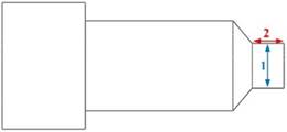
The procedure for recognition and image processing has been successfully implemented, resulting in the automatic calculation of the distance between the tool and the workpiece. This starts by calculating the distance using pixel as units in both X and Z axes as shown in figure 9. However, a calibration technique is implemented to convert the units from pixels to millimeters. The use of image processing in this matter enhances accuracy and reduces the errors as it is detailed in table 3. Finally, the distances in the X and Z directions are automatically added to the G-code part program text before machining. This achieves a complete machine setup, eliminating the need for human intervention. The design and the final machined product are presented in figure 10 a and b, respectively.

Figure 9. The distance between the tool and workpiece

Figure 10. (a) design in solid and (b) the final product
|
Table 3. The effect of using image processing technique |
|||
|
|
Distance without image processing |
Distance with image processing |
Percentage error |
|
z-axis |
28,605 |
32,005 |
10,62 % |
|
X-axis |
16,011 |
20,843 |
23,18 % |
RESULTS
The development of the deep learning algorithm has significantly reduced machining setup time. In experiments, manual setup took approximately 5 minutes, while the proposed deep learning and image processing methodology typically required around 1,5 minutes. However, there is a percentage of error between the design and the final machined product, as detailed in table 4. This error can be minimized through several methods. For example, enriching the dataset with more images can lead to more extensive training and fewer mistakes. Additionally, a more complex training approach, such as using points to specify the tool’s edges instead of a bounding box, can further enhance accuracy and reduce errors.
|
Table 4. The percentage of error between the design and the final machined product of the case study |
|||
|
|
Design part Dimension |
Product Dimension |
Error |
|
|
1: 7,5 mm 2: 5,0 mm |
1: 7,2 mm 2: 4,7 mm |
1: 4 % 2: 6 % |
|
|
3: 14,2 mm 4: 22,5 mm |
3: 14,1 mm 4: 22,1 mm |
3: 0,7 % 4: 1,7 % |

CONCLUSIONS
This paper introduces an automatic machining setup using the YOLO V4 deep learning network and image processing techniques via MATLAB 2022. The application of deep learning involves collecting data by capturing numerous images in the same environment but at different locations. This data is then manually classified into two classes: tool and workpiece. The classified data is used to train the YOLO V4 deep learning network. Subsequently, an initial recognition process is accomplished for both the tools and workpieces. The accuracy of recognizing objects depends on the number of collected images. Following object recognition, image processing is applied to reduce the error in the distance measurement between the tool and workpiece. It involves extracting the bounding boxes of the objects separately and then analyzing these images to enhance the recognition of the tool’s and workpiece’s edges. The image processing phase yields the distance between the tool and workpiece in pixel units. A calibration technique is then applied to convert this measurement to millimeters. The calibration factor is determined by the fixed perpendicular distance between the camera and the machine environment. If this distance changes, the calibration procedure must be repeated. Finally, the resulting distance is added in terms of X and Z coordinates to a block line of the initial G-code automatically. This fully automates the machining setup process without requiring human intervention. While the proposed method has significantly reduced machining setup time and effort, it may still exhibit a small margin of error. This can be minimized by:
· Increasing the number of training images.
· Adopting an alternative approach to specify the tool edges using points instead of bounding boxes.
Regardless of the number of images and the strategy for specifying tool edges, this methodology can be adjusted to suit various applications, including milling and drilling processes.
BIBLIOGRAPHIC REFERENCES
1. N. Rahmatov, A. Paul, F. Saeed, W. H. Hong, H. C. Seo, and J. Kim, “Machine learning–based automated image processing for quality management in industrial internet of things,” International Journal of Distributed Sensor Networks, vol. 15, 10 2019.
2. S. Dutta, S. K. Pal, and R. Sen, “Digital image processing in machining,” pp. 367–410, 2014.
3. V. M. Mohan, R. K. Durga, S. Devathi, and K. S. Raju, “Image processing representation using binary image; grayscale, color image, and histogram, Advances in Intelligent Systems and Computing, vol. 381, pp. 353–361, 2016.
4. M. H. Ryalat, S. V. Khedaskar, M. A. Rokade, B. R. Patil, and T. P. N, “A survey of image processing and identification techniques,” viva-tech international journal for research and innovation, vol. 1, 2018. [Online]. Available: www.viva-technology.org/New/IJRI
5. K. Sumithra, S. Buvana, and R. Somasundaram, “A survey on various types of image processing technique,” International Journal of Engineering Research & Technology (IJERT), vol. 4, 2015. [Online]. Available: www.ijert.org.
6. M. M. K and S. M. B. S, “Object recognition in images,” International Conference on Information Science (ICIS), 2016.
7. R. Oji, “An automatic algorithm for object recognition and detection based on asift keypoints,” Signal & Image Processing : An International Journal, vol.˜3, pp. 29–39, 10 2012.
8. C. Chandrasekar, “Object recognition using svm-knn based on geometric moment invariant,” Article in International Journal of Emerging Trends & Technology in Computer Science, 2011. [Online]. Available: https://www.researchgate.net/publication/236154375
9. M. Bansal, M. Kumar, M. Kumar, and K. Kumar, “An efficient technique for object recognition using shi-tomasi corner detection algorithm,” Soft Computing, vol. 25, pp. 4423–4432, 3 2021.
10. M. Narottambhai and P. Tandel, “A survey on feature extraction techniques for shape based object recognition,” International Journal of Computer Applications, vol. 137, pp. 16–20, 3 2016.
11. K. M. M. Rao, “Overview of image processing.”
12. R. Malathi and S. Ravichandran, “A research survey on real time image processing techniques,” International Journal of Pure and Applied Mathematics, vol. 119, pp. 136–167, 2018. [Online]. Available: http://www.acadpubl.eu/hub/
13. L. Junyan, T. Qingju, W. Yang, L. Yumei, and Z. Zhiping, “Defects’ geometric feature recognition based on infrared image edge detection,” Infrared Physics and Technology, vol. 67, pp. 387–390, 2014.
14. Y. feng Li, X. X. Han, sheng yang Li, and J. Liang, “Non-contact dimension measurement of mechanical parts based on image processing,” 8th International Congress on Image and Signal Processing, 2015.
15. S. Lu, B. Wang, H. Wang, L. Chen, M. Linjian, and X. Zhang, “A real-time object detection algorithm for video,” Computers and Electrical Engineering, vol. 77, pp. 398–408, 7 2019.
16. S. Patel, N. Patel, S. Deshpande, and A. Siddiqui, “Ship intrusion detection using custom object detection system with yolo algorithm,” International Research Journal of Engineering and Technology, 2021. [Online]. Available: www.irjet.net
17. M. L. Francies, M. M. Ata, and M. A. Mohamed, “A robust multiclass 3d object recognition based on modern yolo deep learning algorithms,” Concurrency and Computation: Practice and Experience, vol. 34, 1 2022.
18. H. Fujiyoshi, T. Hirakawa, and T. Yamashita, “Deep learning-based image recognition for autonomous driving,” IATSS Research, vol. 43, pp. 244–252, 12 2019.
19. W. Zhiqiang and L. Jun, “A review of object detection based on convolutional neural network,” Proceedings of the 36th Chinese Control Conference, 2017.
20. Sunil and Gagandeep, “Study of object detection methods and applications on digital images,” IJSDR1905088 International Journal of Scientific Development and Research, 2019. [Online]. Available: www.ijsdr.org
21. N. V. Nguyen, C. Rigaud, and J. C. Burie, “Semi-supervised object detection with unlabeled data,” vol. 5. SciTePress, 2019, pp. 289–296.
22. C. Liu, Y. Tao, J. Liang, K. Li, and Y. Chen, “Object detection based on yolo network,” 2018.
23. J. Kaur and W. Singh, “Tools, techniques, datasets and application areas for object detection in an image: a review,” Multimedia Tools and Applications, vol. 81, pp. 38 297–38 351, 11 2022.
24. T. Diwan, G. Anirudh, and J. V. Tembhurne, “Object detection using yolo: challenges, architectural successors, datasets and applications,” Multimedia Tools and Applications, vol. 82, pp. 9243–9275, 3 2023.
25. J. Redmon, S. Divvala, R. Girshick, and A. Farhadi, “You only look once: Unified, real-time object detection,” IEEE Eplore. [Online]. Available: http://pjreddie.com/yolo/
26. X. Wu, Y. Liu, X. Zhou, and A. Mou, “Automatic identification of tool wear based on convolutional neural network in face milling process,” Sensors (Switzerland), vol. 19, 9 2019.
27. P. Ong, W. K. Lee, and R. J. H. Lau, “Tool condition monitoring in cnc end milling using wavelet neural network based on machine vision,” International Journal of Advanced Manufacturing Technology, vol. 104, pp. 1369–1379, 9 2019.
28. W. J. Lin, J. W. Chen, J. P. Jhuang, M. S. Tsai, C. L. Hung, and K. M. Li, “Integrating object detection and image segmentation for detecting the tool wear area on stitched image,” Scientific Reports, vol. 11, 12 2021.
29. N. Sharma, V. K. Chawla, and N. Ram, “Comparison of machine learning algorithms for the automatic programming of computer numerical control machine,” International Journal of Data and Network Science, vol. 4, pp. 1–14, 12 2020.
30. S. Zhang, C. Qu, C. Ru, X. Wang, and Z. Li, “Multi-objects recognition and self-explosion defect detection method for insulators based on lightweight ghostnet-yolov4 model deployed on board uav,” IEEE Access, 2023.
31. P. Jiang, D. Ergu, F. Liu, Y. Cai, and B. Ma, “A review of yolo algorithm developments,” Procedia Computer Science, vol. 199, pp. 1066–1073, 2021.
32. K. Saranya, J. J. R. Jegaraj, K. R. Kumar, and G. V. Rao, “Artificial intelligence based selection of optimal cutting tool and process parameters for effective turning and milling operations,” Journal of The Institution of Engineers (India): Series C, vol. 99, pp. 381–392, 8 2018.
33. C. Limberg, A. Melnik, H. Ritter, and H. Prendinger, “Yolo: You only look 10647 times.” INSTICC, 3 2023, pp. 153–160.
34. S. Mohammad, “Object detection and recognition in image processing,” International Journal of Management, vol. 8, 2018. [Online]. Available: http://www.ijmra.us
FINANCING
There is no specific funding to support this research.
CONFLICT OF INTEREST
All authors reviewed the results, approved the final version of the manuscript and agreed to publish it.
AUTHORSHIP CONTRIBUTION
Conceptualization: Weam A. Al-khaleeli, Mohanned M. H. AL-Khafaji, Mazin Al-Wswasi.
Data curation: Weam A. Al-khaleeli, Mohanned M. H. AL-Khafaji, Mazin Al-Wswasi.
Formal analysis: Weam A. Al-khaleeli, Mohanned M. H. AL-Khafaji, Mazin Al-Wswasi.
Research: Weam A. Al-khaleeli, Mohanned M. H. AL-Khafaji, Mazin Al-Wswasi.
Methodology: Weam A. Al-khaleeli, Mohanned M. H. AL-Khafaji, Mazin Al-Wswasi.
Drafting - original draft: Weam A. Al-khaleeli, Mohanned M. H. AL-Khafaji, Mazin Al-Wswasi.
Writing - proofreading and editing: Weam A. Al-khaleeli, Mohanned M. H. AL-Khafaji, Mazin Al-Wswasi.